- 您现在的位置:买卖IC网 > PDF目录69018 > MAX6917EO30 (MAXIM INTEGRATED PRODUCTS INC) REAL TIME CLOCK, PDSO20 PDF资料下载
参数资料
| 型号: | MAX6917EO30 |
| 厂商: | MAXIM INTEGRATED PRODUCTS INC |
| 元件分类: | 时钟/数据恢复及定时提取 |
| 英文描述: | REAL TIME CLOCK, PDSO20 |
| 封装: | 0.150 INCH, 0.025 INCH PITCH, MO-137AD, QSOP-20 |
| 文件页数: | 16/31页 |
| 文件大小: | 349K |
| 代理商: | MAX6917EO30 |
第1页第2页第3页第4页第5页第6页第7页第8页第9页第10页第11页第12页第13页第14页第15页当前第16页第17页第18页第19页第20页第21页第22页第23页第24页第25页第26页第27页第28页第29页第30页第31页
MAX6917
I2C-Compatible RTC with Microprocessor
Supervisor, Alarm, and NV RAM Controller
______________________________________________________________________________________
23
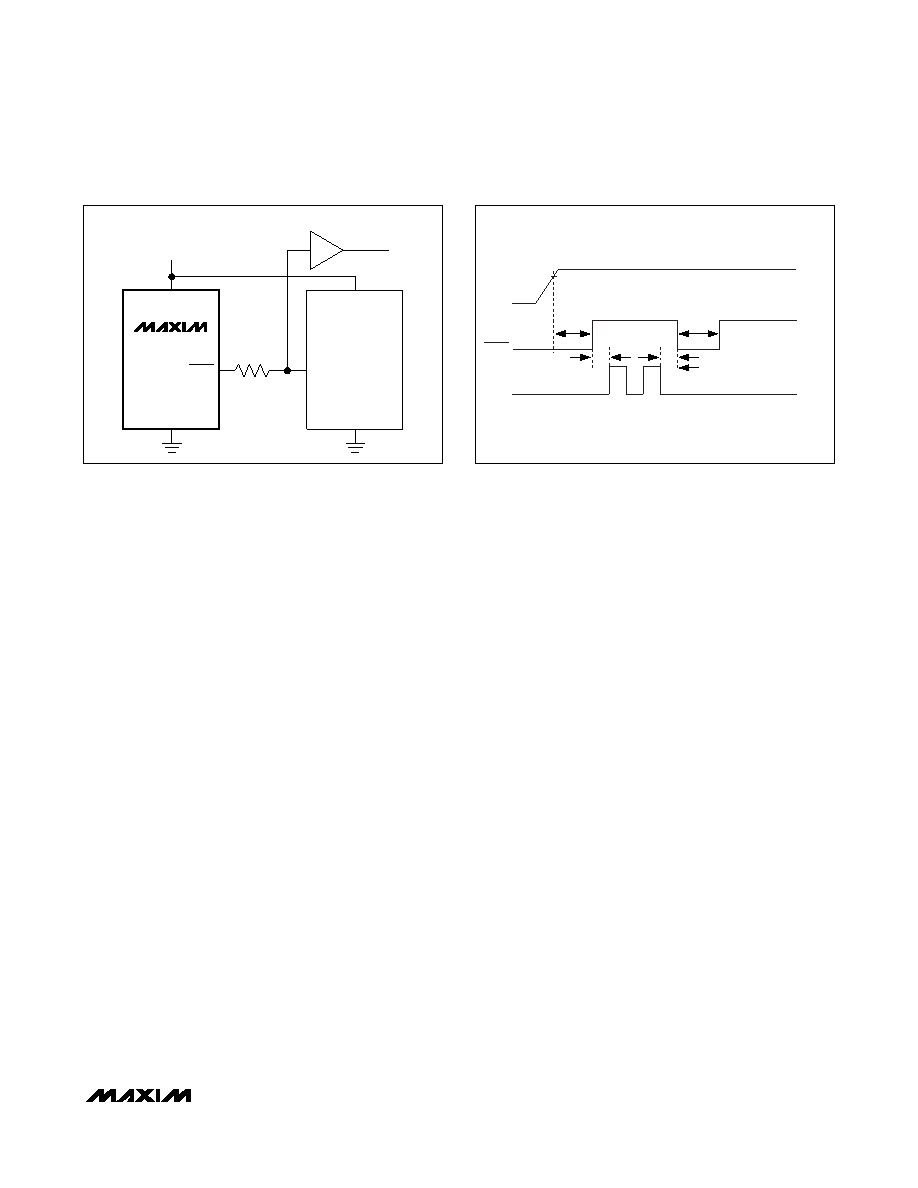
Interfacing to Ps with Bidirectional
Reset Pins
Microprocessors with bidirectional reset pins, such as
the Motorola 68HC11 series, can contend with the
MAX6917 RESET output. If, for example, the RESET
output is driven high and the P wants to pull it low,
indeterminate logic levels can result. To correct this,
connect a 4.7k
resistor between the RESET output
and the P reset I/O as shown in Figure 11. Buffer the
RESET output to other system components.
Battery-On Output
The battery-on output, BATT_ON, is an open-drain out-
put that indicates when the MAX6917 is powered from
the backup-battery input, VBATT. When VCC falls below
the reset threshold, VRST, and below VBATT, VOUT
switches from VCC to VBATT and BATT_ON becomes
low. When VCC rises above the reset threshold, VRST,
VOUT reconnects to VCC and BATT_ON becomes high
(open-drain output with pullup resistor). If desired, the
BATT_ON output can be register selected, through the
BATT ON BLINK bit in the control register, to toggle on
and off 0.5s on, 0.5s off when active. The POR default
is logic zero for no blink.
Watchdog Input
The watchdog circuit monitors the P’s activity. If the
P does not toggle the watchdog input (WDI) within the
register-selectable watchdog-timeout period, RESET is
asserted for tRP. At the same time, the WD EN and WD
TIME bits in the control register (Table 1) are reset to
zero and can only be set again by writing the appropri-
ate command to the control register. Thus, once a
RESET is asserted due to a watchdog timeout, the
watchdog function is disabled (Figure 12).
WDI can detect pulses as short as tWDI. Data bit D2 in
the control register controls the selection of the watch-
dog-timeout period. The power-up default is 1.6s (D2 =
0). A reset condition returns the timeout to 1.6s (D2 =
0). If D2 is set to one, then the watchdog-timeout period
is changed to 200ms. Data bit D3 in the control register
is the watchdog-enable function. A logic zero disables
the watchdog function, while a logic one enables it. The
POR state of WD EN is logic one, or the watchdog func-
tion is enabled. Disable the watchdog function by writ-
ing a zero to the WD EN bit in the control register,
within the 1.6s POR default timeout after power-up.
WDI does not include a pulldown or pullup feature. For
this reason, WDI should not be left floating. When the
WD EN bit in the control register is set to zero, WDI
should be connected to VCC or GND. WDI is disabled
and does not draw cross-conduction current when VCC
falls below VRST.
Watchdog Software Considerations
There is a way to help the watchdog-timer monitor soft-
ware execution more closely, which involves setting and
resetting the watchdog input at different points in the
program rather than “pulsing” the watchdog input. This
technique avoids a “stuck” loop, in which the watchdog
timer would continue to be reset within the loop, keeping
the watchdog from timing out. Figure 13 shows an
example of a flow diagram where the I/O driving the
watchdog input is set high at the beginning of the pro-
gram, set low at the beginning of every subroutine or
loop, then set high again when the program returns to
the beginning. If the program should “hang” in any sub-
routine, the problem would quickly be corrected since
the I/O is continually set low and the watchdog timer is
allowed to time out, causing a reset to be issued.
MAX6917
VCC
GND
VCC
GND
RESET
BUFFER
4.7k
P
VCC
Figure 11. Interfacing to P with Bidirectional Reset I/O
VRST
VCC
RESET
WDI
tRP
tWD
WD EN AND WD TIME ARE SET
TO ZERO AND THE WATCHDOG
FUNCTION IS DISABLED.
Figure 12. Watchdog Timing Diagram
相关PDF资料 |
PDF描述 |
|---|---|
| MAX6917EO33 | REAL TIME CLOCK, PDSO20 |
| MAX8893AEWV+ | SPECIALTY MICROPROCESSOR CIRCUIT, PBGA30 |
| MAX8893BEWV+ | SPECIALTY MICROPROCESSOR CIRCUIT, PBGA30 |
| MAX8893CEWV+ | SPECIALTY MICROPROCESSOR CIRCUIT, PBGA30 |
| MAX9485ETP+ | 73.728 MHz, OTHER CLOCK GENERATOR, QCC20 |
相关代理商/技术参数 |
参数描述 |
|---|---|
| MAX6917EO30+ | 功能描述:实时时钟 Integrated Circuits (ICs) RoHS:否 制造商:Microchip Technology 功能:Clock, Calendar. Alarm RTC 总线接口:I2C 日期格式:DW:DM:M:Y 时间格式:HH:MM:SS RTC 存储容量:64 B 电源电压-最大:5.5 V 电源电压-最小:1.8 V 最大工作温度:+ 85 C 最小工作温度: 安装风格:Through Hole 封装 / 箱体:PDIP-8 封装:Tube |
| MAX6917EO30+T | 功能描述:实时时钟 Integrated Circuits (ICs) RoHS:否 制造商:Microchip Technology 功能:Clock, Calendar. Alarm RTC 总线接口:I2C 日期格式:DW:DM:M:Y 时间格式:HH:MM:SS RTC 存储容量:64 B 电源电压-最大:5.5 V 电源电压-最小:1.8 V 最大工作温度:+ 85 C 最小工作温度: 安装风格:Through Hole 封装 / 箱体:PDIP-8 封装:Tube |
| MAX6917EO33+ | 功能描述:实时时钟 Integrated Circuits (ICs) RoHS:否 制造商:Microchip Technology 功能:Clock, Calendar. Alarm RTC 总线接口:I2C 日期格式:DW:DM:M:Y 时间格式:HH:MM:SS RTC 存储容量:64 B 电源电压-最大:5.5 V 电源电压-最小:1.8 V 最大工作温度:+ 85 C 最小工作温度: 安装风格:Through Hole 封装 / 箱体:PDIP-8 封装:Tube |
| MAX6917EO33+T | 功能描述:实时时钟 Integrated Circuits (ICs) RoHS:否 制造商:Microchip Technology 功能:Clock, Calendar. Alarm RTC 总线接口:I2C 日期格式:DW:DM:M:Y 时间格式:HH:MM:SS RTC 存储容量:64 B 电源电压-最大:5.5 V 电源电压-最小:1.8 V 最大工作温度:+ 85 C 最小工作温度: 安装风格:Through Hole 封装 / 箱体:PDIP-8 封装:Tube |
| MAX6917EO50 | 功能描述:实时时钟 RoHS:否 制造商:Microchip Technology 功能:Clock, Calendar. Alarm RTC 总线接口:I2C 日期格式:DW:DM:M:Y 时间格式:HH:MM:SS RTC 存储容量:64 B 电源电压-最大:5.5 V 电源电压-最小:1.8 V 最大工作温度:+ 85 C 最小工作温度: 安装风格:Through Hole 封装 / 箱体:PDIP-8 封装:Tube |
发布紧急采购,3分钟左右您将得到回复。