- 您现在的位置:买卖IC网 > PDF目录69018 > MAX6917EO33 (MAXIM INTEGRATED PRODUCTS INC) REAL TIME CLOCK, PDSO20 PDF资料下载
参数资料
| 型号: | MAX6917EO33 |
| 厂商: | MAXIM INTEGRATED PRODUCTS INC |
| 元件分类: | 时钟/数据恢复及定时提取 |
| 英文描述: | REAL TIME CLOCK, PDSO20 |
| 封装: | 0.150 INCH, 0.025 INCH PITCH, MO-137AD, QSOP-20 |
| 文件页数: | 6/31页 |
| 文件大小: | 349K |
| 代理商: | MAX6917EO33 |
第1页第2页第3页第4页第5页当前第6页第7页第8页第9页第10页第11页第12页第13页第14页第15页第16页第17页第18页第19页第20页第21页第22页第23页第24页第25页第26页第27页第28页第29页第30页第31页
MAX6917
I2C-Compatible RTC with Microprocessor
Supervisor, Alarm, and NV RAM Controller
14
______________________________________________________________________________________
Address/Command Byte
The second byte of data sent after the START condition
is the address/command byte (Figure 8). Each data
transfer is initiated by an address/command byte. Bits
7–1 specify the designated register or RAM location to
be read or written to, and the LSB (bit 0) specifies a
write operation if logic zero or a read operation if logic
one. The command byte is always input starting with
the MSB (bit 7).
Reading from the Timekeeping Registers
The timekeeping registers (seconds, minutes, hours,
date, month, day, and year) and the control register
can be read either with a single read or a burst read
(Figure 9). Since the RTC runs continuously and a read
takes a finite amount of time, there is the possibility that
the clock counters could change during a read opera-
tion, thereby reporting inaccurate timekeeping data. In
the MAX6917, each clock counter’s data is buffered by
a latch. Clock counter data is latched by the I2C bus
read command (on the falling edge of SCL when the
slave acknowledge bit is sent, after the address/com-
mand byte has been sent by the master to read a time-
keeping register). Collision-detection circuitry ensures
that this does not happen coincident with a seconds
counter update to ensure accurate time data is being
read. This avoids time-data changes during a read
operation. The clock counters continue to count and
keep accurate time during the read operation.
If single reads are used to read each of the timekeep-
ing registers individually, then it is necessary to do
some error checking on the receiving end. An error can
occur when the seconds counter increments before all
the other registers are read out. For example, suppose
a carry of 13:59:59 to 14:00:00 occurs during single-
read operations of the timekeeping registers. Then the
net data could become 14:59:59, which is erroneous
real-time data. To prevent this with single-read opera-
tions, read the seconds register first (initial seconds)
and store this value for future comparison. When the
remaining timekeeping registers have been read out,
read the seconds register again (final seconds). If the
initial seconds value is 59, check that the final-seconds
value is still 59; if not, repeat the entire single-read
process for the timekeeping registers. A comparison of
the initial-seconds value with the final-seconds value
can indicate if there was a bus-delay problem in read-
ing the timekeeping data (difference should always be
1s or less). Using a 100kHz bus speed, and sequential
single reads, it would take under 2.5ms to read all
seven of the timekeeping registers plus a second read
of the seconds register.
The most accurate way to read the timekeeping regis-
ters is to perform a burst read. With burst reads, the
main timekeeping registers (seconds, minutes, hours,
date, month, day, year) and the control register are
read sequentially, in the order listed with the seconds
register first. They must be all read out as a group of
SDA
SCL
MASTER
TRANSMITTER/
RECEIVER
SLAVE
RECEIVER
SLAVE
TRANSMITTER/
RECEIVER
MASTER
TRANSMITTER
MASTER
TRANSMITTER/
RECEIVER
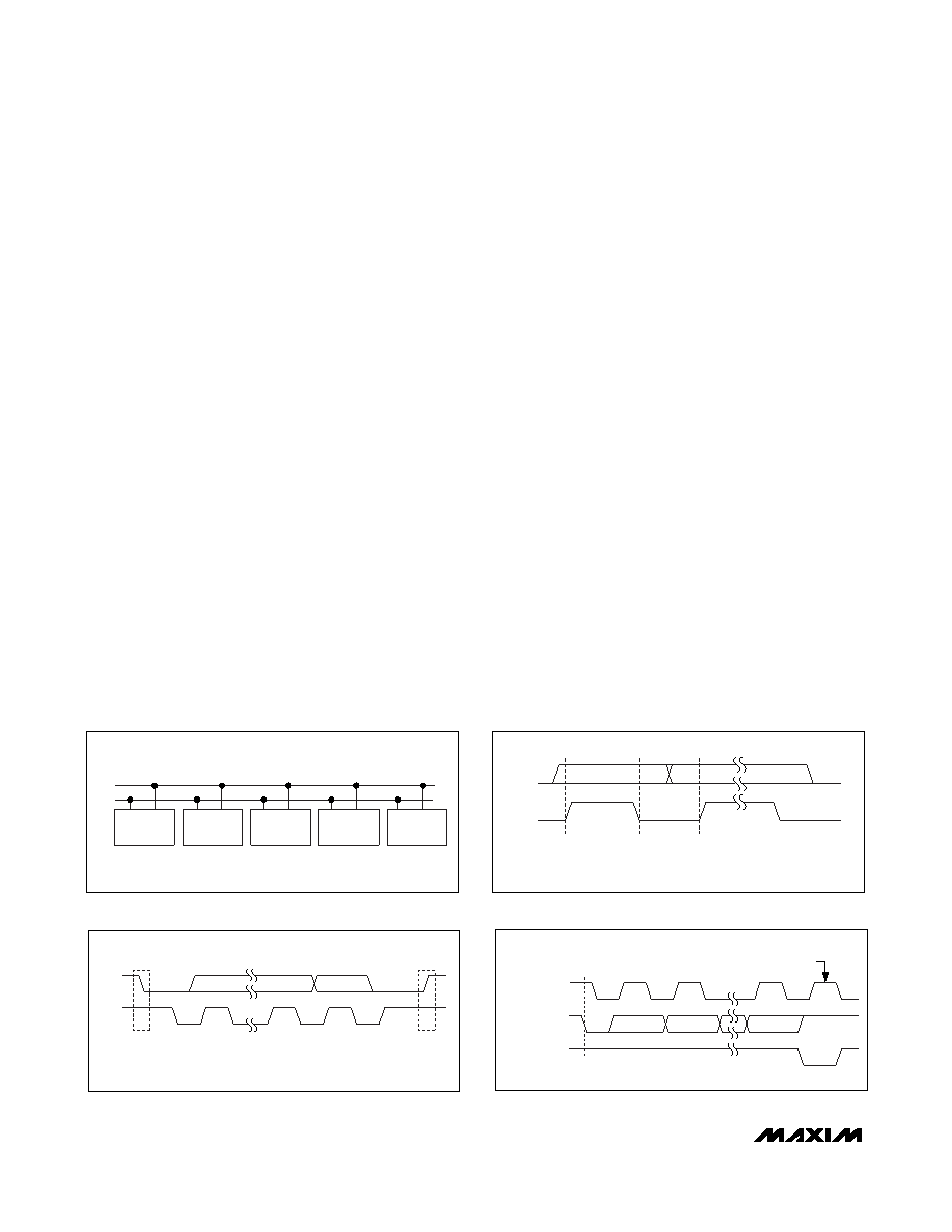
Figure 3. I2C System Configuration
SDA
SCL
START
CONDITION
STOP
CONDITION
SP
Figure 4. START and STOP Conditions
SDA
SCL
DATA LINE
STABLE;
DATA VALID
CHANGE OF
DATA
ALLOWED
Figure 5. Bit Transfer
SCL
SDA
BY TRANSMITTER
CLOCK PULSE FOR
ACKNOWLEDGE
START
CONDITION
SDA
BY RECEIVER
12
89
S
Figure 6. Acknowledge
相关PDF资料 |
PDF描述 |
|---|---|
| MAX8893AEWV+ | SPECIALTY MICROPROCESSOR CIRCUIT, PBGA30 |
| MAX8893BEWV+ | SPECIALTY MICROPROCESSOR CIRCUIT, PBGA30 |
| MAX8893CEWV+ | SPECIALTY MICROPROCESSOR CIRCUIT, PBGA30 |
| MAX9485ETP+ | 73.728 MHz, OTHER CLOCK GENERATOR, QCC20 |
| MAXQ1004-B01+ | RISC MICROCONTROLLER, QCC16 |
相关代理商/技术参数 |
参数描述 |
|---|---|
| MAX6917EO33+ | 功能描述:实时时钟 Integrated Circuits (ICs) RoHS:否 制造商:Microchip Technology 功能:Clock, Calendar. Alarm RTC 总线接口:I2C 日期格式:DW:DM:M:Y 时间格式:HH:MM:SS RTC 存储容量:64 B 电源电压-最大:5.5 V 电源电压-最小:1.8 V 最大工作温度:+ 85 C 最小工作温度: 安装风格:Through Hole 封装 / 箱体:PDIP-8 封装:Tube |
| MAX6917EO33+T | 功能描述:实时时钟 Integrated Circuits (ICs) RoHS:否 制造商:Microchip Technology 功能:Clock, Calendar. Alarm RTC 总线接口:I2C 日期格式:DW:DM:M:Y 时间格式:HH:MM:SS RTC 存储容量:64 B 电源电压-最大:5.5 V 电源电压-最小:1.8 V 最大工作温度:+ 85 C 最小工作温度: 安装风格:Through Hole 封装 / 箱体:PDIP-8 封装:Tube |
| MAX6917EO50 | 功能描述:实时时钟 RoHS:否 制造商:Microchip Technology 功能:Clock, Calendar. Alarm RTC 总线接口:I2C 日期格式:DW:DM:M:Y 时间格式:HH:MM:SS RTC 存储容量:64 B 电源电压-最大:5.5 V 电源电压-最小:1.8 V 最大工作温度:+ 85 C 最小工作温度: 安装风格:Through Hole 封装 / 箱体:PDIP-8 封装:Tube |
| MAX6917EO50+ | 功能描述:实时时钟 RoHS:否 制造商:Microchip Technology 功能:Clock, Calendar. Alarm RTC 总线接口:I2C 日期格式:DW:DM:M:Y 时间格式:HH:MM:SS RTC 存储容量:64 B 电源电压-最大:5.5 V 电源电压-最小:1.8 V 最大工作温度:+ 85 C 最小工作温度: 安装风格:Through Hole 封装 / 箱体:PDIP-8 封装:Tube |
| MAX6917EO50+T | 功能描述:实时时钟 Integrated Circuits (ICs) RoHS:否 制造商:Microchip Technology 功能:Clock, Calendar. Alarm RTC 总线接口:I2C 日期格式:DW:DM:M:Y 时间格式:HH:MM:SS RTC 存储容量:64 B 电源电压-最大:5.5 V 电源电压-最小:1.8 V 最大工作温度:+ 85 C 最小工作温度: 安装风格:Through Hole 封装 / 箱体:PDIP-8 封装:Tube |
发布紧急采购,3分钟左右您将得到回复。