- 您现在的位置:买卖IC网 > PDF目录15957 > MAX691ACWE+ (Maxim Integrated Products)IC MPU SUPERVISOR CIRCUIT 16SOIC PDF资料下载
参数资料
| 型号: | MAX691ACWE+ |
| 厂商: | Maxim Integrated Products |
| 文件页数: | 9/17页 |
| 文件大小: | 0K |
| 描述: | IC MPU SUPERVISOR CIRCUIT 16SOIC |
| 产品培训模块: | Lead (SnPb) Finish for COTS Obsolescence Mitigation Program |
| 标准包装: | 46 |
| 类型: | 备用电池电路 |
| 监视电压数目: | 1 |
| 输出: | 推挽式,推挽式 |
| 复位: | 高有效/低有效 |
| 复位超时: | 最小为 140 ms |
| 电压 - 阀值: | 4.65V |
| 工作温度: | 0°C ~ 70°C |
| 安装类型: | 表面贴装 |
| 封装/外壳: | 16-SOIC(0.295",7.50mm 宽) |
| 供应商设备封装: | 16-SOIC W |
| 包装: | 管件 |
| 产品目录页面: | 1412 (CN2011-ZH PDF) |
�� �
�
�Microprocessor� Supervisory� Circuits�
�Table� 1.� Reset� Pulse� Width� and� Watchdog� Timeout� Selections�
�OSC� SEL�
�OSC� IN�
�Watchdog� Timeout� Period�
�Normal� Immediately� After� Reset�
�Reset� Timeout� Period�
�Low�
�Low�
�Floating�
�Floating�
�External� Clock� Input�
�External� Capacitor�
�Low�
�Floating�
�1024� clks�
�(600/47pF� x� C)ms�
�100ms�
�1.6s�
�4096� clks�
�(2.4/47pF� x� C)sec�
�1.6s�
�1.6s�
�2048� clks�
�(1200/47pF� x� C)ms�
�200ms�
�200ms�
�In� the� high-impedance� mode,� the� leakage� currents� into�
�low-impedance� mode,� the� impedance� of� CE� IN� appears�
�drive� to� CE� IN� and� the� capacitive� loading� on� the� Chip-�
�Enable� Output� (� CE� OUT)� (see� Chip-Enable� Propagation�
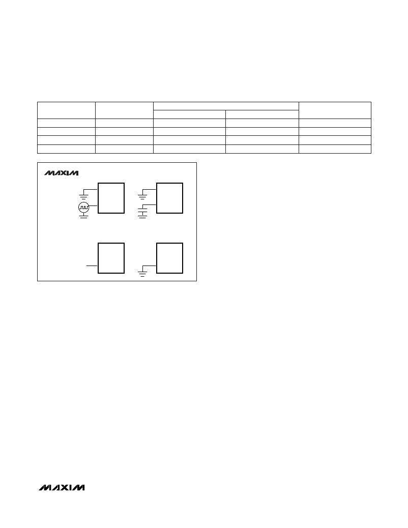
�MAX691A�
�MAX693A�
�MAX800L�
�MAX800M�
�50kHz�
�8�
�7�
�EXTERNAL�
�CLOCK�
�OSC� SEL�
�OSC� IN�
�8�
�7�
�EXTERNAL�
�OSCILLATOR�
�OSC� SEL�
�OSC� IN�
�this� terminal� are� ±1μA� max� over� temperature.� In� the�
�–�
�as� a� 75� Ω� resistor� in� series� with� the� load� at� CE� OUT.�
�The� propagation� delay� through� the� CE� transmission�
�gate� depends� on� both� the� source� impedance� of� the�
�–�
�–�
�Delay� vs.� CE� OUT� Load� Capacitance� in� the� Typical�
�is� production� tested� from� the� 50%� point� of� CE� IN� to� the�
�50%� point� of� CE� OUT� using� a� 50� Ω� driver� and� 50pF� of�
�N.C.�
�INTERNAL� OSCILLATOR�
�1.6s� WATCHDOG�
�8�
�OSC� SEL�
�N.C.�
�INTERNAL� OSCILLATOR�
�100ms� WATCHDOG�
�8�
�OSC� SEL�
�Operating� Characteristics).� The� CE� propagation� delay�
�–�
�–�
�load� capacitance� (Figure� 6).� For� minimum� propagation�
�N.C.�
�7�
�OSC� IN�
�7�
�OSC� IN�
�delay,� minimize� the� capacitive� load� at� CE� OUT,� and�
�use� a� low� output-impedance� driver.�
�Chip-Enable� Output�
�these� parts� use� a� series� transmission� gate� from� CE� IN� to�
�During� a� power-down� sequence� where� V� CC� falls� below�
�the� reset� threshold� or� a� watchdog� fault,� CE� IN� assumes�
�Figure 3. Oscillator Circuits�
�Chip-Enable� Signal� Gating�
�The� MAX691A/MAX693A/MAX800L/MAX800M� provide�
�internal� gating� of� chip-enable� (CE)� signals� to� prevent�
�erroneous� data� from� being� written� to� CMOS� RAM� in� the�
�event� of� a� power� failure.� During� normal� operation,� the�
�CE� gate� is� enabled� and� passes� all� CE� transitions.� When�
�reset� is� asserted,� this� path� becomes� disabled,� prevent-�
�ing� erroneous� data� from� corrupting� the� CMOS� RAM.� All�
�–�
�CE� OUT� (Figure� 4).�
�The� 10ns� max� CE� propagation� delay� from� CE� IN� to� CE�
�OUT� enables� the� parts� to� be� used� with� most� μPs.�
�Chip-Enable� Input�
�The� Chip-Enable� Input� (� CE� IN)� is� high� impedance� (dis-�
�abled� mode)� while� RESET� and� RESET� are� asserted.�
�–�
�a� high-impedance� state� when� the� voltage� at� CE� IN�
�goes� high� or� 15μs� after� reset� is� asserted,� whichever�
�occurs� first� (Figure� 5).�
�During� a� power-up� sequence,� CE� IN� remains� high�
�impedance,� regardless� of� CE� IN� activity,� until� reset� is�
�deasserted� following� the� reset� timeout� period.�
�In� the� enabled� mode,� the� impedance� of� CE� OUT� is�
�equivalent� to� 75� Ω� in� series� with� the� source� driving� CE�
�IN.� In� the� disabled� mode,� the� 75� Ω� transmission� gate� is�
�off� and� CE� OUT� is� actively� pulled� to� V� OUT� .� This� source�
�turns� off� when� the� transmission� gate� is� enabled.�
�– –�
�—� —� —� —� —�
�L� O� W� L� I� N� E� Output�
�LOW� LINE� is� the� buffered� output� of� the� reset� threshold�
�comparator.� LOW� LINE� typically� sinks� 3.2mA� at� 0.1V.�
�For� normal� operation� (V� CC� above� the� LOW� LINE� thresh-�
�old),� LOW� LINE� is� pulled� to� V� OUT� .�
�Power-Fail� Comparator�
�The� power-fail� comparator� is� an� uncommitted� comparator�
�that� has� no� effect� on� the� other� functions� of� the� IC.�
�Common� uses� include� low-battery� indication� (Figure� 7),�
�and� early� power-fail� warning� (see� Typical� Operating�
�Circuit).�
�Power-Fail� Input�
�Power-Fail� Input� (PFI)� is� the� input� to� the� power-fail� com-�
�parator.� It� has� a� guaranteed� input� leakage� of� ±25nA�
�max� over� temperature.� The� typical� comparator� delay� is�
�25μs� from� V� IL� to� V� OL� (power� failing),� and� 60μs� from� V� IH�
�to� V� OH� (power� being� restored).� If� PFI� is� not� used,� con-�
�nect� it� to� ground.�
�_______________________________________________________________________________________�
�9�
�相关PDF资料 |
PDF描述 |
|---|---|
| MAX691ACSE+ | IC SUPERVISOR MPU 16-SOIC |
| M3CKK-6018R | IDC CABLE - MKC60K/MC60M/MPK60K |
| MAX693ACSE+ | IC SUPERVISOR MPU 16-SOIC |
| RP10-4815DE/N/M1 | CONV DC/DC 10W 36-75VIN +/-15V |
| M3AKK-6018R | IDC CABLE - MSC60K/MC60M/MPK60K |
相关代理商/技术参数 |
参数描述 |
|---|---|
| MAX691ACWE+ | 功能描述:监控电路 MPU Supervisor RoHS:否 制造商:STMicroelectronics 监测电压数: 监测电压: 欠电压阈值: 过电压阈值: 输出类型:Active Low, Open Drain 人工复位:Resettable 监视器:No Watchdog 电池备用开关:No Backup 上电复位延迟(典型值):10 s 电源电压-最大:5.5 V 最大工作温度:+ 85 C 安装风格:SMD/SMT 封装 / 箱体:UDFN-6 封装:Reel |
| MAX691ACWE+T | 功能描述:监控电路 MPU Supervisor RoHS:否 制造商:STMicroelectronics 监测电压数: 监测电压: 欠电压阈值: 过电压阈值: 输出类型:Active Low, Open Drain 人工复位:Resettable 监视器:No Watchdog 电池备用开关:No Backup 上电复位延迟(典型值):10 s 电源电压-最大:5.5 V 最大工作温度:+ 85 C 安装风格:SMD/SMT 封装 / 箱体:UDFN-6 封装:Reel |
| MAX691ACWE-T | 功能描述:监控电路 RoHS:否 制造商:STMicroelectronics 监测电压数: 监测电压: 欠电压阈值: 过电压阈值: 输出类型:Active Low, Open Drain 人工复位:Resettable 监视器:No Watchdog 电池备用开关:No Backup 上电复位延迟(典型值):10 s 电源电压-最大:5.5 V 最大工作温度:+ 85 C 安装风格:SMD/SMT 封装 / 箱体:UDFN-6 封装:Reel |
| MAX691AEJE | 功能描述:监控电路 RoHS:否 制造商:STMicroelectronics 监测电压数: 监测电压: 欠电压阈值: 过电压阈值: 输出类型:Active Low, Open Drain 人工复位:Resettable 监视器:No Watchdog 电池备用开关:No Backup 上电复位延迟(典型值):10 s 电源电压-最大:5.5 V 最大工作温度:+ 85 C 安装风格:SMD/SMT 封装 / 箱体:UDFN-6 封装:Reel |
| MAX691AEPA | 制造商:Maxim Integrated Products 功能描述: |
发布紧急采购,3分钟左右您将得到回复。