- 您现在的位置:买卖IC网 > PDF目录20740 > MAX6964AEG+T (Maxim Integrated)IC LED DRIVER LINEAR 24-QSOP PDF资料下载
参数资料
| 型号: | MAX6964AEG+T |
| 厂商: | Maxim Integrated |
| 文件页数: | 14/23页 |
| 文件大小: | 0K |
| 描述: | IC LED DRIVER LINEAR 24-QSOP |
| 产品培训模块: | Lead (SnPb) Finish for COTS Obsolescence Mitigation Program |
| 标准包装: | 2,500 |
| 拓扑: | 开路漏极,PWM |
| 输出数: | 17 |
| 内部驱动器: | 是 |
| 类型 - 主要: | 背光,LED 闪烁器 |
| 类型 - 次要: | RGB,白色 LED |
| 频率: | 400kHz |
| 电源电压: | 2 V ~ 3.6 V |
| 输出电压: | 7V |
| 安装类型: | 表面贴装 |
| 封装/外壳: | 24-SSOP(0.154",3.90mm 宽) |
| 供应商设备封装: | 24-QSOP |
| 包装: | 带卷 (TR) |
| 工作温度: | -40°C ~ 125°C |
�� �
�
�17-Output� LED� Driver/GPO� with�
�Intensity� Control� and� Hot-Insertion� Protection�
�PWM� Intensity� Control�
�The� MAX6964� includes� an� internal� oscillator,� nominally�
�32kHz,� to� generate� PWM� timing� for� LED� intensity� control�
�or� other� applications� such� as� PWM� trim� DACs.� PWM� can�
�be� disabled� entirely� for� all� the� outputs.� In� this� case,� all�
�outputs� are� static� and� the� MAX6964� operating� current� is�
�lowest� because� the� internal� PWM� oscillator� is� turned� off.�
�The� MAX6964� can� be� configured� to� provide� any� combi-�
�nation� of� PWM� outputs� and� glitch-free� logic� outputs.�
�Each� PWM� output� has� an� individual� 4-bit� intensity� con-�
�trol� (Table� 12).� When� all� outputs� are� to� be� used� with� the�
�same� PWM� setting,� the� outputs� can� be� controlled�
�together� instead� using� the� global� intensity� control�
�(Table� 11).� Table� 8� shows� how� to� set� up� the� MAX6964�
�to� suit� a� particular� application.�
�PWM� Timing�
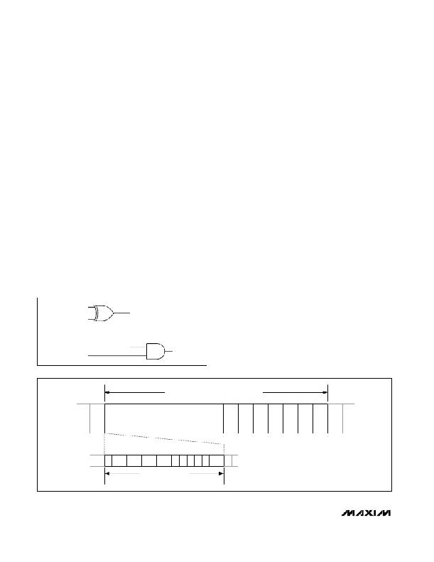
�The� PWM� control� uses� a� 240-step� PWM� period,� divided�
�into� 15� master� intensity� timeslots.� Each� master� intensity�
�timeslot� is� divided� further� into� 16� PWM� cycles� (Figure� 12).�
�The� master� intensity� operates� as� a� gate,� allowing� the� indi-�
�vidual� output� settings� to� be� enabled� from� 1� to� 15� timeslots�
�per� PWM� period� (Figures� 13,� 14,� and� 15)� (Table� 11).�
�Each� output� ’s� individual� 4-bit� intensity� control� only�
�operates� during� the� number� of� timeslots� gated� by� the�
�BLINK� ENABLE� FLAG� E�
�BLINK� FLIP� FLAG� B�
�master� intensity.� The� individual� controls� provide� 16�
�intensity� settings� from� 1/16� through� 16/16� (Table� 12).�
�Figures� 16,� 17,� and� 18� show� examples� of� individual�
�intensity� control� settings.� The� highest� value� an� individ-�
�ual� or� global� setting� can� be� set� to� is� 16/16.� This� setting�
�forces� the� output� to� ignore� the� master� control,� and� fol-�
�low� the� logic� level� set� by� the� appropriate� blink� phase�
�register� bit.� The� output� becomes� a� glitch-free� static� out-�
�put� with� no� PWM.�
�Using� PWM� Intensity� Controls� with� Blink� Disabled�
�When� blink� is� disabled� (Table� 5),� the� blink� phase� 0� regis-�
�ters� specify� each� output’s� logic� level� during� the� PWM� on-�
�time� (Table� 6).� The� effect� of� setting� an� output’s� blink�
�phase� 0� register� bit� to� zero� or� 1� is� shown� in� Table� 9.� With�
�its� output� bit� set� to� zero,� an� LED� can� be� controlled� with� 16�
�intensity� settings� from� 1/16th� duty� through� fully� on,� but�
�cannot� be� turned� fully� off� using� the� PWM� intensity� control.�
�With� its� output� bit� set� to� 1,� an� LED� can� be� controlled� with�
�16� intensity� settings� from� fully� off� through� 15/16th� duty.�
�Using� PWM� Intensity� Controls� with� Blink� Enabled�
�When� blink� is� enabled� (Table� 5),� the� blink� phase� 0� regis-�
�ters� and� blink� phase� 1� registers� specify� each� output’s�
�logic� level� during� the� PWM� on-time� during� the� respective�
�blink� phases� (Tables� 6� and� 7).� The� effect� of� setting� an�
�output’s� blink� phase� x� register� bit� to� 0� or� 1� is� shown� in�
�Table� 10.� LEDs� can� be� flipped� between� either� directly� on�
�and� off,� or� between� a� variety� of� high/low� PWM� intensities.�
�Global/O16� Intensity� Control�
�The� 4� bits� used� for� output� O16’s� PWM� individual� inten-�
�sity� setting� also� double� as� the� global� intensity� control�
�(Table� 11).� Global� intensity� simplifies� the� PWM� settings�
�BLINK� INPUT�
�Figure� 11.� BLINK� Logic�
�BLINK� PHASE�
�REGISTERS�
�when� the� application� requires� them� all� to� be� the� same,�
�such� as� for� backlight� applications,� by� replacing� the� 17�
�individual� settings� with� one� setting.� Global� intensity� is�
�ONE� PWM� PERIOD� IS� 240� CYCLES� OF� THE� 32kHz� PWM�
�OSCILLATOR;� A� PWM� PERIOD� CONTAINS� 15� MASTER�
�INTENSITY� TIMESLOTS�
�14�
�15�
�1�
�2�
�3�
�4�
�5�
�6�
�7�
�8�
�9�
�10�
�11�
�12�
�13�
�14�
�15�
�1�
�2�
�15� 16� 1�
�2�
�3�
�4�
�5�
�6�
�7�
�8�
�9� 10� 11� 12� 13� 14� 15� 16�
�1�
�2�
�EACH� MASTER� INTENSITY�
�TIMESLOT� CONTAINS� 16�
�PWM� CYCLES�
�Figure� 12.� PWM� Timing�
�14�
�______________________________________________________________________________________�
�相关PDF资料 |
PDF描述 |
|---|---|
| 0805PC153KAT1A | CAP CER 0.015UF 250V X7R 0805 |
| MAX8648ETE+ | IC LED DRVR WT/RGB BCKLGT 16TQFN |
| TPSV687K006R0050 | CAP TANT 680UF 6.3V 10% 2924 |
| MAX6946CAWE+T | IC LED DRIVER LINEAR 16-WLP |
| RS3B-13 | RECT FAST RECOVERY 100V 3A SMC |
相关代理商/技术参数 |
参数描述 |
|---|---|
| MAX6964ATG | 功能描述:LED显示驱动器 17-Output LED Driver/GPO RoHS:否 制造商:Micrel 数位数量:5 片段数量: 安装风格:SMD/SMT 封装 / 箱体:PLCC-44 工作电源电压:4.75 V to 11 V 最大电源电流:10 mA 最大工作温度:+ 85 C 最小工作温度:- 40 C 封装:Tube |
| MAX6964ATG+ | 功能描述:LED显示驱动器 17-Output LED Driver/GPO RoHS:否 制造商:Micrel 数位数量:5 片段数量: 安装风格:SMD/SMT 封装 / 箱体:PLCC-44 工作电源电压:4.75 V to 11 V 最大电源电流:10 mA 最大工作温度:+ 85 C 最小工作温度:- 40 C 封装:Tube |
| MAX6964ATG+T | 功能描述:LED显示驱动器 17-Output LED Driver/GPO RoHS:否 制造商:Micrel 数位数量:5 片段数量: 安装风格:SMD/SMT 封装 / 箱体:PLCC-44 工作电源电压:4.75 V to 11 V 最大电源电流:10 mA 最大工作温度:+ 85 C 最小工作温度:- 40 C 封装:Tube |
| MAX6964ATG-T | 功能描述:LED显示驱动器 17-Output LED Driver/GPO RoHS:否 制造商:Micrel 数位数量:5 片段数量: 安装风格:SMD/SMT 封装 / 箱体:PLCC-44 工作电源电压:4.75 V to 11 V 最大电源电流:10 mA 最大工作温度:+ 85 C 最小工作温度:- 40 C 封装:Tube |
| MAX6964EVCMAXQUSB | 功能描述:LED 照明开发工具 Evaluation Kit for the MAX6964 RoHS:否 制造商:Fairchild Semiconductor 产品:Evaluation Kits 用于:FL7732 核心: 电源电压:120V 系列: 封装: |
发布紧急采购,3分钟左右您将得到回复。