- 您现在的位置:买卖IC网 > PDF目录20165 > MAX7221CWG+T (Maxim Integrated)IC DRVR DSPLY LED 8DIG 24SOIC PDF资料下载
参数资料
| 型号: | MAX7221CWG+T |
| 厂商: | Maxim Integrated |
| 文件页数: | 10/17页 |
| 文件大小: | 0K |
| 描述: | IC DRVR DSPLY LED 8DIG 24SOIC |
| 产品培训模块: | Lead (SnPb) Finish for COTS Obsolescence Mitigation Program |
| 标准包装: | 1,000 |
| 显示器类型: | LED |
| 配置: | 7 段 + DP |
| 接口: | 4 线串行 |
| 数字或字符: | 8 位数字 |
| 电流 - 电源: | 330mA |
| 电源电压: | 4 V ~ 5.5 V |
| 工作温度: | 0°C ~ 70°C |
| 安装类型: | 表面贴装 |
| 封装/外壳: | 24-SOIC(0.295",7.50mm 宽) |
| 供应商设备封装: | 24-SOIC W |
| 包装: | 带卷 (TR) |
�� �
�
�MAX7219/MAX7221�
�Serially� Interfaced,� 8-Digit� LED� Display� Drivers�
�If� the� scan-limit� register� is� set� for� three� digits� or� less,�
�individual� digit� drivers� will� dissipate� excessive� amounts�
�of� power.� Consequently,� the� value� of� the� R� SET� resistor�
�must� be� adjusted� according� to� the� number� of� digits� dis-�
�played,� to� limit� individual� digit� driver� power� dissipation.�
�Table� 9� lists� the� number� of� digits� displayed� and� the�
�corresponding� maximum� recommended� segment� cur-�
�rent� when� the� digit� drivers� are� used.�
�Display-Test� Register�
�The� display-test� register� operates� in� two� modes:� normal�
�and� display� test.� Display-test� mode� turns� all� LEDs� on�
�by� overriding,� but� not� altering,� all� controls� and� digit� reg-�
�isters� (including� the� shutdown� register).� In� display-test�
�mode,� 8� digits� are� scanned� and� the� duty� cycle� is� 31/32�
�(15/16� for� MAX7221).� Table� 10� lists� the� display-test� reg-�
�ister� format.�
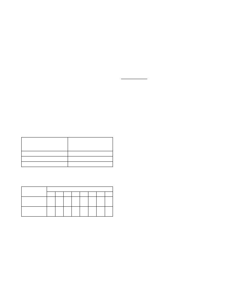
�Table� 9.� Maximum� Segment� Current� for�
�1-,� 2-,� or� 3-Digit� Displays�
�fourth� chip,� sent� the� desired� 16-bit� word,� followed� by�
�three� no-op� codes� (hex� 0xXX0X,� see� Table� 2).� When�
�LOAD/� CS� goes� high,� data� is� latched� in� all� devices.� The�
�first� three� chips� receive� no-op� commands,� and� the�
�fourth� receives� the� intended� data.�
�Applications� Information�
�Supply� Bypassing� and� Wiring�
�To� minimize� power-supply� ripple� due� to� the� peak� digit�
�driver� currents,� connect� a� 10μF� electrolytic� and� a� 0.1μF�
�ceramic� capacitor� between� V+� and� GND� as� close� to�
�the� device� as� possible.� The� MAX7219/MAX7221� should�
�be� placed� in� close� proximity� to� the� LED� display,� and�
�connections� should� be� kept� as� short� as� possible� to�
�minimize� the� effects� of� wiring� inductance� and� electro-�
�magnetic� interference.� Also,� both� GND� pins� must� be�
�connected� to� ground.�
�Selecting� R� SET� Resistor� and�
�Using� External� Drivers�
�NUMBER� OF� DIGITS�
�DISPLAYED�
�1�
�2�
�3�
�MAXIMUM� SEGMENT�
�CURRENT�
�(mA)�
�10�
�20�
�30�
�The� current� per� segment� is� approximately� 100� times�
�the� current� in� ISET.� To� select� R� SET� ,� see� Table� 11.� The�
�MAX7219/MAX7221’s� maximum� recommended� seg-�
�ment� current� is� 40mA.� For� segment� current� levels�
�above� these� levels,� external� digit� drivers� will� be� need-�
�ed.� In� this� application,� the� MAX7219/MAX7221� serve�
�only� as� controllers� for� other� high-current� drivers� or� tran-�
�sistors.� Therefore,� to� conserve� power,� use� R� SET� =� 47k� Ω�
�when� using� external� current� sources� as� segment� dri-�
�Table� 10.� Display-Test� Register� Format�
�(Address� (Hex)� =� 0xXF)�
�vers.�
�The� example� in� Figure� 2� uses� the� MAX7219/MAX7221’s�
�segment� drivers,� a� MAX394� single-pole� double-throw�
�MODE�
�Normal�
�Operation�
�D7�
�X�
�D6�
�X�
�REGISTER� DATA�
�D5� D4� D3� D2�
�X� X� X� X�
�D1�
�X�
�D0�
�0�
�analog� switch,� and� external� transistors� to� drive� 2.3”�
�AND2307SLC� common-cathode� displays.� The� 5.6V�
�zener� diode� has� been� added� in� series� with� the� decimal�
�point� LED� because� the� decimal� point� LED� forward� volt-�
�age� is� typically� 4.2V.� For� all� other� segments� the� LED�
�Display� Test�
�Mode�
�X�
�X�
�X�
�X�
�X�
�X�
�X�
�1�
�forward� voltage� is� typically� 8V.� Since� external� transis-�
�tors� are� used� to� sink� current� (DIG� 0� and� DIG� 1� are� used�
�Note:� The� MAX7219/MAX7221� remain� in� display-test� mode�
�(all� LEDs� on)� until� the� display-test� register� is� reconfigured�
�for� normal� operation.�
�No-Op� Register�
�The� no-op� register� is� used� when� cascading� MAX7219s�
�or� MAX7221s.� Connect� all� devices’� LOAD/� CS� inputs�
�together� and� connect� DOUT� to� DIN� on� adjacent�
�devices.� DOUT� is� a� CMOS� logic-level� output� that� easily�
�drives� DIN� of� successively� cascaded� parts.� (Refer� to�
�the� Serial� Addressing� Modes� section� for� detailed� infor-�
�mation� on� serial� input/output� timing.)� For� example,� if�
�four� MAX7219s� are� cascaded,� then� to� write� to� the�
�10�
�as� logic� switches),� peak� segment� currents� of� 45mA� are�
�allowed� even� though� only� two� digits� are� displayed.� In�
�applications� where� the� MAX7219/MAX7221’s� digit� dri-�
�vers� are� used� to� sink� current� and� fewer� than� four� digits�
�are� displayed,� Table� 9� specifies� the� maximum� allow-�
�able� segment� current.� R� SET� must� be� selected� accord-�
�ingly� (Table� 11).�
�Refer� to� the� Continuous� Power� Dissipation� section� of�
�the� Absolute� Maximum� Ratings� to� calculate� acceptable�
�limits� for� ambient� temperature,� segment� current,� and�
�the� LED� forward-voltage� drop.�
�Maxim� Integrated�
�相关PDF资料 |
PDF描述 |
|---|---|
| VI-24V-EV-F1 | CONVERTER MOD DC/DC 5.8V 150W |
| IDT71V424YL12PHI | IC SRAM 4MBIT 12NS 44TSOP |
| T95R227K016CSSL | CAP TANT 220UF 16V 10% 2824 |
| PSAA60W-120-R-C2 | ADAPTER DESKTOP CLASS II 60W 12V |
| ACB11DHLR | CONN EDGECARD 22POS .050 DIP SLD |
相关代理商/技术参数 |
参数描述 |
|---|---|
| MAX7221ENG | 功能描述:LED显示驱动器 8-Digit LED Display Driver RoHS:否 制造商:Micrel 数位数量:5 片段数量: 安装风格:SMD/SMT 封装 / 箱体:PLCC-44 工作电源电压:4.75 V to 11 V 最大电源电流:10 mA 最大工作温度:+ 85 C 最小工作温度:- 40 C 封装:Tube |
| MAX7221ENG+ | 功能描述:LED显示驱动器 8-Digit LED Display Driver RoHS:否 制造商:Micrel 数位数量:5 片段数量: 安装风格:SMD/SMT 封装 / 箱体:PLCC-44 工作电源电压:4.75 V to 11 V 最大电源电流:10 mA 最大工作温度:+ 85 C 最小工作温度:- 40 C 封装:Tube |
| MAX7221ERG | 功能描述:LED显示驱动器 RoHS:否 制造商:Micrel 数位数量:5 片段数量: 安装风格:SMD/SMT 封装 / 箱体:PLCC-44 工作电源电压:4.75 V to 11 V 最大电源电流:10 mA 最大工作温度:+ 85 C 最小工作温度:- 40 C 封装:Tube |
| MAX7221EWG | 功能描述:LED显示驱动器 RoHS:否 制造商:Micrel 数位数量:5 片段数量: 安装风格:SMD/SMT 封装 / 箱体:PLCC-44 工作电源电压:4.75 V to 11 V 最大电源电流:10 mA 最大工作温度:+ 85 C 最小工作温度:- 40 C 封装:Tube |
| MAX7221EWG+ | 功能描述:LED显示驱动器 8-Digit LED Display Driver RoHS:否 制造商:Micrel 数位数量:5 片段数量: 安装风格:SMD/SMT 封装 / 箱体:PLCC-44 工作电源电压:4.75 V to 11 V 最大电源电流:10 mA 最大工作温度:+ 85 C 最小工作温度:- 40 C 封装:Tube |
发布紧急采购,3分钟左右您将得到回复。