- 您现在的位置:买卖IC网 > PDF目录11137 > MAX7357ETG+T (Maxim Integrated Products)IC MULTIPLEXER 8X1 24TQFN PDF资料下载
参数资料
| 型号: | MAX7357ETG+T |
| 厂商: | Maxim Integrated Products |
| 文件页数: | 3/22页 |
| 文件大小: | 0K |
| 描述: | IC MULTIPLEXER 8X1 24TQFN |
| 产品培训模块: | Lead (SnPb) Finish for COTS Obsolescence Mitigation Program |
| 标准包装: | 2,500 |
| 功能: | 多路复用器 |
| 电路: | 1 x 8:1 |
| 电压电源: | 单电源 |
| 电压 - 电源,单路/双路(±): | 2.3 V ~ 5.5 V |
| 工作温度: | -40°C ~ 85°C |
| 安装类型: | 表面贴装 |
| 封装/外壳: | 24-WFQFN 裸露焊盘 |
| 供应商设备封装: | 24-TQFN-EP(4x4) |
| 包装: | 带卷 (TR) |
MAX7356/MAX7357/MAX7358
1-to-8 I2C Bus Switches/Multiplexers with Bus
Lock-Up Detection, Isolation, and Notification
______________________________________________________________________________________
11
Bus Lock-Up Detection, Isolation,
and Notification Operation
(MAX7357/MAX7358)
SDA Stuck Low
If either line of any downstream bus is low for a period
exceeding 25ms between t1 and t2 in Figure 6, the
MAX7357/MAX7358 detect a lock-up fault on that bus
and takes the action configured by the user. If the lock-
up is not on the main bus, SDA and SCL return to the
high state at the same time. The MAX7357 or MAX7358
then identifies which SD_ or SC_ is still pulled low. If the
optional interrupt function is enabled (by setting B0 of
the configuration register), an active-low interrupt is
generated at
RST/INT.
If B4 in the configuration register is set to 1, then only
faults on connected buses cause the MAX7357 or
MAX7358 to disconnect all buses from each other.
When this is the case, faults detected on disconnected
buses set the flag in the lock-up status register, and, if
enabled, notify the host of the fault, but do not discon-
nect the buses from one another.
B1 of the configuration register enables the flush-out
sequence. If this bit is set to 1, the MAX7357 or
MAX7358 attempts to send a flush-out sequence over
the locked SD_ and SC_ pair (the sequence begins at
t5 in Figure 6). If the flush-out sequence is successful,
the locked bus (SD_ and SC_) is released at t6 (Figure
6). The I2C master (at SDA and SCL) reads the
MAX7357 or MAX7358 lock-up status register to iden-
tify the locked-up bus. If
RST/INT is enabled as an
interrupt, it is released once a read command to the
lock-up indication register is received by the MAX7357
or MAX7358 (shown at t7 in Figure 6). The RST/INT
can also be automatically released after a 1.6s delay
by setting bit 2 of the configuration register.
Preconnection Wiggle Test
(Stuck High Fault)
(MAX7357/MAX7358)
By setting bit B7 in the configuration register to 1, a pre-
connection wiggle test is enabled for all downstream
buses. This test only runs on the downstream bus when
the bus is selected through the switch control register.
Enabling this test does not affect any bus that is already
connected to the host bus; however, deselecting and
subsequently reselecting the bus will cause the test to
occur. The test is performed when the switch control reg-
ister bit (or bits if multiple buses are selected in the same
I2C transaction) toggles from 0 to 1 and a stop condition
is received. It consists of the MAX7357 or MAX7358
pulling the downstream clock line low, then the down-
stream data line low. Both lines are checked for a nomi-
nal low value, and then the clock line is released followed
by the data line (Note: This is an I2C stop condition and
is seen by any I2C devices connected to the extended
bus). If either the clock or data line (or both) fail to pull
low during the test, the MAX7357 or MAX7358 do not
allow that downstream bus to connect to the host. If the
optional interrupt notification bit is set (B0), the device
notifies the host that a fault has occurred. The I2C master
can then read the MAX7357 or MAX7358 registers to find
out which bus or buses caused the fault. Faults detected
by this test are stored in the preconnection fault register
(0x06). The stuck high Fault register is cleared once this
register is read, resetting the device, or disabling the
preconnection test.
Device Address
The MAX7356/MAX7357/MAX7358 family of devices
has selectable device addresses through three external
inputs. The slave address consists of 4 fixed bits
(A6–A3 set to 1110); followed by 3 pin-programmable
bits (A2, A1, A0), as shown in Figure 7. The addresses
A2, A1, and A0 can also be driven dynamically if
required, but the values must be stable when they are
expected in the address sequence.
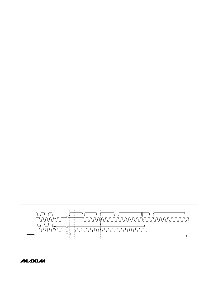
RST/INT
BYTE1
FLUSH-OUT DATA
NOTE: THE FLUSH-OUT SEQUENCE RUNS AT AN SC_ FREQUENCY OF 40kHz.
THE HOST MAY COMMUNICATE AT UP TO 400kHz. THE TIMING SHOWN IS NOT TO SCALE.
BYTE4
t1
t2
t3
t4 t5
t6
t7
SDA
SCL
SD_
SC_
Figure 6. Bus Lock-Up Detection, Isolation, and Notification Timing Diagram
相关PDF资料 |
PDF描述 |
|---|---|
| MAX7357EUG+T | IC MULTIPLEXER 8X1 24TSSOP |
| VI-BWY-IW-F2 | CONVERTER MOD DC/DC 3.3V 66W |
| MAX4527CSA+T | IC SWITCH DUAL SPDT 8SOIC |
| VE-J6D-IW-F2 | CONVERTER MOD DC/DC 85V 100W |
| VI-BWX-IY-F3 | CONVERTER MOD DC/DC 5.2V 50W |
相关代理商/技术参数 |
参数描述 |
|---|---|
| MAX7357EUG+ | 功能描述:多路器开关 IC 1-to-8 I2C Bus Switch/MUX RoHS:否 制造商:Texas Instruments 通道数量:1 开关数量:4 开启电阻(最大值):7 Ohms 开启时间(最大值): 关闭时间(最大值): 传播延迟时间:0.25 ns 工作电源电压:2.3 V to 3.6 V 工作电源电流: 最大工作温度:+ 85 C 安装风格:SMD/SMT 封装 / 箱体:UQFN-16 |
| MAX7357EUG+T | 功能描述:多路器开关 IC 1-to-8 I2C Bus Switch/MUX RoHS:否 制造商:Texas Instruments 通道数量:1 开关数量:4 开启电阻(最大值):7 Ohms 开启时间(最大值): 关闭时间(最大值): 传播延迟时间:0.25 ns 工作电源电压:2.3 V to 3.6 V 工作电源电流: 最大工作温度:+ 85 C 安装风格:SMD/SMT 封装 / 箱体:UQFN-16 |
| MAX7358ETG+ | 功能描述:多路器开关 IC 1-to-8 I2C Bus Switch/MUX RoHS:否 制造商:Texas Instruments 通道数量:1 开关数量:4 开启电阻(最大值):7 Ohms 开启时间(最大值): 关闭时间(最大值): 传播延迟时间:0.25 ns 工作电源电压:2.3 V to 3.6 V 工作电源电流: 最大工作温度:+ 85 C 安装风格:SMD/SMT 封装 / 箱体:UQFN-16 |
| MAX7358ETG+T | 功能描述:多路器开关 IC 1-to-8 I2C Bus Switch/MUX RoHS:否 制造商:Texas Instruments 通道数量:1 开关数量:4 开启电阻(最大值):7 Ohms 开启时间(最大值): 关闭时间(最大值): 传播延迟时间:0.25 ns 工作电源电压:2.3 V to 3.6 V 工作电源电流: 最大工作温度:+ 85 C 安装风格:SMD/SMT 封装 / 箱体:UQFN-16 |
| MAX7358EUG+ | 功能描述:多路器开关 IC 1-to-8 I2C Bus Switch/MUX RoHS:否 制造商:Texas Instruments 通道数量:1 开关数量:4 开启电阻(最大值):7 Ohms 开启时间(最大值): 关闭时间(最大值): 传播延迟时间:0.25 ns 工作电源电压:2.3 V to 3.6 V 工作电源电流: 最大工作温度:+ 85 C 安装风格:SMD/SMT 封装 / 箱体:UQFN-16 |
发布紧急采购,3分钟左右您将得到回复。