- 您现在的位置:买卖IC网 > PDF目录11669 > MAX7360ETL+ (Maxim Integrated Products)IC CTRLR KEY-SW I2C 40TQFN-EP PDF资料下载
参数资料
| 型号: | MAX7360ETL+ |
| 厂商: | Maxim Integrated Products |
| 文件页数: | 8/32页 |
| 文件大小: | 0K |
| 描述: | IC CTRLR KEY-SW I2C 40TQFN-EP |
| 产品培训模块: | Lead (SnPb) Finish for COTS Obsolescence Mitigation Program |
| 标准包装: | 60 |
| 类型: | 控制器 |
| 输入类型: | 逻辑 |
| 输出类型: | 逻辑 |
| 接口: | I²C,2 线串口 |
| 电流 - 电源: | 50µA |
| 安装类型: | 表面贴装 |
| 封装/外壳: | 40-WFQFN 裸露焊盘 |
| 供应商设备封装: | 40-TQFN-EP(5x5) |
| 包装: | 管件 |
第1页第2页第3页第4页第5页第6页第7页当前第8页第9页第10页第11页第12页第13页第14页第15页第16页第17页第18页第19页第20页第21页第22页第23页第24页第25页第26页第27页第28页第29页第30页第31页第32页
16
Maxim Integrated
I2C-Interfaced Key-Switch Controller and LED
Driver/GPIOs with Integrated ESD Protection
MAX7360
transaction, either read or write, if SCL low exceeds
20ms. After a bus timeout, the MAX7360 waits for a valid
START condition before responding to a consecutive
transmission. This feature can be enabled or disabled
under user control by writing to the configuration register
(Table 8 in the Register Tables section).
Message Format for Writing
the Key-Scan Controller
A write to the MAX7360 comprises the transmission of the
slave address with the R/W bit set to zero, followed by at
least 1 byte of information. The first byte of information
is the command byte. The command byte determines
which register of the MAX7360 is to be written by the next
byte, if received. If a STOP condition is detected after the
command byte is received, the MAX7360 takes no further
action (Figure 7) beyond storing the command byte.
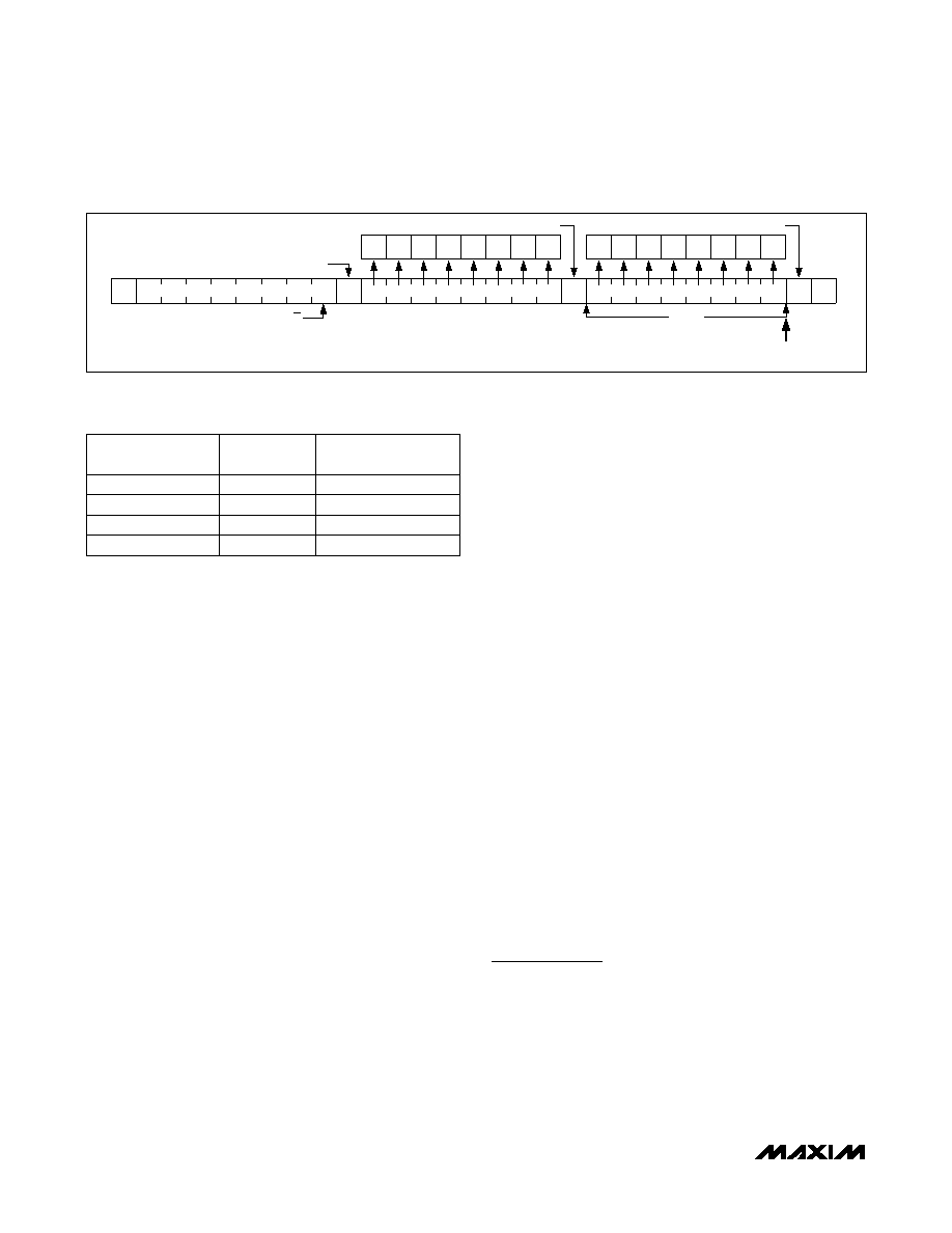
Any bytes received after the command byte are data bytes.
The first data byte goes into the internal register of the
MAX7360 selected by the command byte (Figure 8).
If multiple data bytes are transmitted before a STOP condi-
tion is detected, these bytes are generally stored in subse-
quent MAX7360 internal registers, because the command
byte address generally autoincrements (Table 4).
Message Format for Reading
the Key-Scan Controller
The MAX7360 is read using the internally stored com-
mand byte as an address pointer, the same way the
stored command byte is used as an address pointer
for a write. The pointer generally autoincrements after
each data byte is read using the same rules as for a
write (Table 4). Thus, a read is initiated by first config-
uring the MAX7360’s command byte by performing a
write (Figure 7). The master can now read n consecutive
bytes from the MAX7360, with the first data byte being
read from the register addressed by the initialized com-
mand byte. When performing read-after-write verifica-
tion, remember to reset the command byte’s address,
because the stored command byte address is generally
autoincremented after the write (Figure 9, Table 4).
Operation with Multiple Masters
When the MAX7360 is operated on a 2-wire interface
with multiple masters, a master reading the MAX7360
uses a repeated start between the write that sets the
MAX7360’s address pointer, and the read(s) that takes
the data from the location(s). This is because it is pos-
sible for master 2 to take over the bus after master 1 has
set up the MAX7360’s address pointer, but before mas-
ter 1 has read the data. If master 2 subsequently resets
the MAX7360’s address pointer, master 1’s read can be
from an unexpected location.
Command Address Autoincrementing
Address autoincrementing allows the MAX7360 to be
configured with fewer transmissions by minimizing the
number of times the command address needs to be
sent. The command address stored in the MAX7360
generally increments after each data byte is written or
read (Table 4). Autoincrement only works when doing a
multiburst read or write.
Applications Information
Reset from I2C
After a catastrophic event such as ESD discharge or
microcontroller reset, use bit D7 of the configuration
register (0x01) as a software reset for the key-switch
state (the key-switch register values and FIFO remain
unaffected). Use bit D4 of the GPIO global configura-
tion register (0x40) as a software reset for the GPIOs.
Figure 9. N Data Bytes Received
Table 4. Autoincrement Rules
REGISTER
FUNCTION
ADDRESS
CODE (hex)
AUTOINCREMENT
ADDRESS (hex)
Keys FIFO
0x00
Autoshutdown
0x06
0x00
All other key switch
0x01 to 0x05
Addr + 0x01
All other GPIO
0x40 to 0x5F
Addr + 0x01
S
A
P
0
SLAVE ADDRESS
COMMAND BYTE
DATA BYTE
N BYTES
AUTOINCREMENT
COMMAND BYTE ADDRESS
D7
D6
D5
D4
D3
D2
D1
D0
D1
D0
D3
D2
D5
D4
D7
D6
ACKNOWLEDGE FROM MAX7360
R/W
相关PDF资料 |
PDF描述 |
|---|---|
| DS1878T+ | IC CTLR SFP W/DGTL LDD RX 28TQFN |
| MAX9621AUB+ | IC HALL EFFECT SENSOR 10UMAX |
| VI-J40-IW-F1 | CONVERTER MOD DC/DC 5V 100W |
| AD2S82ALPZ | IC CONV R/D MONO VAR RES 44PLCC |
| VI-J40-IW-F2 | CONVERTER MOD DC/DC 5V 100W |
相关代理商/技术参数 |
参数描述 |
|---|---|
| MAX7360ETL+ | 功能描述:外围驱动器与原件 - PCI Key-Switch Ctlr & LED Driver/GPIO RoHS:否 制造商:PLX Technology 工作电源电压: 最大工作温度: 安装风格:SMD/SMT 封装 / 箱体:FCBGA-1156 封装:Tray |
| MAX7360ETL+T | 功能描述:外围驱动器与原件 - PCI Key-Switch Ctlr & LED Driver/GPIO RoHS:否 制造商:PLX Technology 工作电源电压: 最大工作温度: 安装风格:SMD/SMT 封装 / 箱体:FCBGA-1156 封装:Tray |
| MAX7360EVKIT+ | 制造商:Maxim Integrated Products 功能描述:I2C-INTERFACED KEY-SWITCH CONTROLLE - Boxed Product (Development Kits) |
| MAX7360EWX+ | 制造商:MAXIM 制造商全称:Maxim Integrated Products 功能描述:I2C-Interfaced Key-Switch Controller and LED Driver/GPIOs with Integrated ESD Protection |
| MAX7360EWX+T | 功能描述:外围驱动器与原件 - PCI Key-Switch Ctlr & LED Driver/GPIO RoHS:否 制造商:PLX Technology 工作电源电压: 最大工作温度: 安装风格:SMD/SMT 封装 / 箱体:FCBGA-1156 封装:Tray |
发布紧急采购,3分钟左右您将得到回复。