- 您现在的位置:买卖IC网 > PDF目录13580 > MAX860IUA+T (Maxim Integrated Products)IC REG SWITCHD CAP DBL INV 8UMAX PDF资料下载
参数资料
| 型号: | MAX860IUA+T |
| 厂商: | Maxim Integrated Products |
| 文件页数: | 8/11页 |
| 文件大小: | 0K |
| 描述: | IC REG SWITCHD CAP DBL INV 8UMAX |
| 产品培训模块: | Lead (SnPb) Finish for COTS Obsolescence Mitigation Program |
| 标准包装: | 2,500 |
| 类型: | 切换式电容器(充电泵),倍增器,反相 |
| 输出类型: | 可调式 |
| 输出数: | 1 |
| 输出电压: | -1.5 V ~ -5.5 V,3 V ~ 11 V |
| 输入电压: | 1.5 V ~ 5.5 V |
| 频率 - 开关: | 6kHz,50kHz,130kHz |
| 电流 - 输出: | 50mA |
| 同步整流器: | 无 |
| 工作温度: | -25°C ~ 85°C |
| 安装类型: | 表面贴装 |
| 封装/外壳: | 8-TSSOP,8-MSOP(0.118",3.00mm 宽) |
| 包装: | 带卷 (TR) |
| 供应商设备封装: | 8-uMAX |
�� �
�
�MAX860/MAX861�
�50mA,� Frequency-Selectable,�
�Switched-Capacitor� Voltage� Converters�
�Flying� Capacitor,� C1�
�Increasing� the� size� of� the� flying� capacitor� reduces� the�
�output� resistance.�
�Output� Capacitor,� C2�
�Increasing� the� size� of� the� output� capacitor� reduces� the�
�output� ripple� voltage.� Decreasing� its� ESR� reduces� both�
�output� resistance� and� ripple.� Smaller� capacitance� val-�
�ues� can� be� used� if� one� of� the� higher� switching� frequen-�
�cies� is� selected,� if� less� than� the� maximum� rated� output�
�current� (50mA)� is� required,� or� if� higher� ripple� can� be�
�tolerated.� The� following� equation� for� peak-to-peak� rip-�
�ple� applies� to� both� the� inverter� and� doubler� circuits.�
�I� OUT�
�V� RIPPLE� =� ————————� +� 2� x� I� OUT� x� ESR� C2�
�2� x� f� S� x� C2�
�Bypass� Capacitor�
�Bypass� the� incoming� supply� to� reduce� its� AC� impedance�
�and� the� impact� of� the� MAX860/MAX861� ’s� switching�
�noise.� The� recommended� bypassing� depends� on� the� cir-�
�cuit� configuration� and� where� the� load� is� connected.�
�When� the� inverter� is� loaded� from� OUT� to� GND� or� the�
�doubler� is� loaded� from� V� DD� to� GND,� current� from� the�
�supply� switches� between� 2� x� I� OUT� and� zero.� Therefore,�
�use� a� large� bypass� capacitor� (e.g.,� equal� to� the� value�
�of� C1)� if� the� supply� has� a� high� AC� impedance.�
�When� the� inverter� and� doubler� are� loaded� from� V� DD� to�
�OUT,� the� circuit� draws� 2� x� I� OUT� constantly,� except� for�
�short� switching� spikes.� A� 0.1μF� bypass� capacitor� is�
�sufficient.�
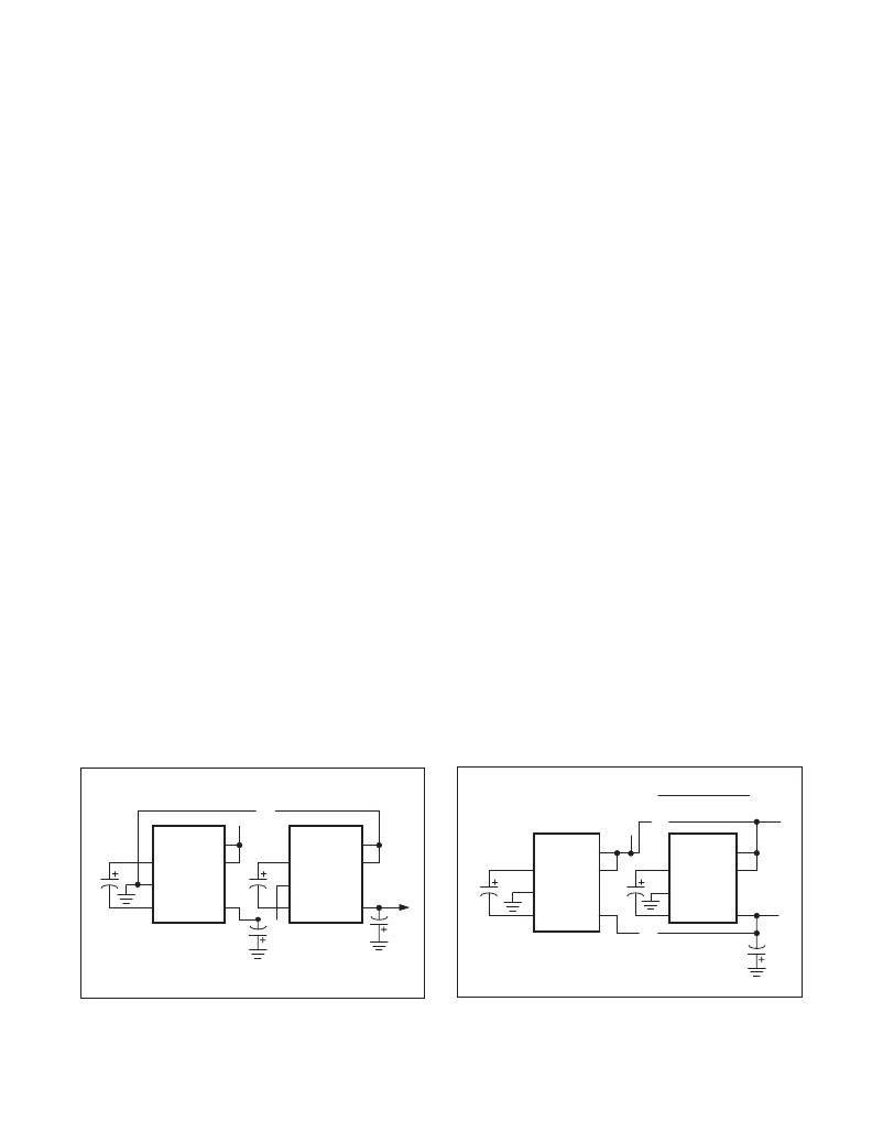
�Cascading� Devices�
�Two� devices� can� be� cascaded� to� produce� an� even�
�larger� negative� voltage,� as� shown� in� Figure� 1.� The�
�unloaded� output� voltage� is� nominally� -2� x� V� IN� ,� but� this� is�
�reduced� slightly� by� the� output� resistance� of� the� first�
�device� multiplied� by� the� quiescent� current� of� the� sec-�
�ond.� The� output� resistance� of� the� complete� circuit� is�
�approximately� five� times� the� output� resistance� of� a� sin-�
�gle� MAX860/MAX861.�
�Three� or� more� devices� can� be� cascaded� in� this� way,�
�but� output� resistance� rises� dramatically,� and� a� better�
�solution� is� offered� by� inductive� switching� regulators�
�(such� as� the� MAX755,� MAX759,� MAX764,� or� MAX774).�
�Connect� LV� as� with� a� standard� inverter� circuit� (see� Pin�
�Description).�
�The� maximum� load� current� and� startup� current� of� nth�
�cascaded� circuit� must� not� exceed� the� maximum� output�
�current� capability� of� (n-1)th� circuit� to� ensure� proper�
�startup.�
�Paralleling� Devices�
�Paralleling� multiple� MAX860s� or� MAX861s� reduces� the�
�output� resistance.� As� illustrated� in� Figure� 2,� each�
�device� requires� its� own� pump� capacitor� (C1),� but� the�
�reservoir� capacitor� (C2)� serves� all� devices.� C2’s� value�
�should� be� increased� by� a� factor� of� n,� where� n� is� the�
�number� of� devices.� Figure� 2� shows� the� equation� for� cal-�
�culating� output� resistance.� An� alternative� solution� is� to�
�use� the� MAX660� or� MAX665,� which� are� capable� of� sup-�
�plying� up� to� 100mA� of� load� current.� Connect� LV� as� with�
�a� standard� inverter� circuit� (see� Pin� Description).�
�Combined� Doubler/Inverter�
�In� the� circuit� of� Figure� 3,� capacitors� C1� and� C2� form� the�
�inverter,� while� C3� and� C4� form� the� doubler.� C1� and� C3�
�are� the� pump� capacitors;� C2� and� C4� are� the� reservoir�
�capacitors.� Because� both� the� inverter� and� doubler� use�
�part� of� the� charge-pump� circuit,� loading� either� output�
�causes� both� outputs� to� decline� towards� GND.� Make�
�8�
�…�
�+V� IN�
�8�
�8�
�R� OUT� OF SINGLE DEVICE�
�R� OUT� =� NUMBER� OF� DEVICES�
�…�
�+V� IN�
�8�
�C1�
�2�
�3�
�4�
�MAX860�
�MAX861�
�“1”�
�7�
�5�
�C1�
�2�
�3�
�4�
�…�
�C2�
�MAX860�
�MAX861�
�“n”�
�7�
�5�
�V� OUT�
�C2�
�C1�
�2�
�3�
�4�
�MAX860�
�MAX861�
�“1”�
�7�
�5�
�C1�
�…�
�2�
�3�
�4�
�MAX860�
�MAX861�
�“n”�
�7�
�5�
�V� OUT�
�V� OUT� =� -nV� IN�
�V� OUT� =� -V� IN�
�C2�
�Figure� 1.� Cascading� MAX860s� or� MAX861s� to� Increase�
�Output� Voltage�
�8�
�Figure� 2.� Paralleling� MAX860s� or� MAX861s� to� Reduce� Output�
�Resistance�
�Maxim� Integrated�
�相关PDF资料 |
PDF描述 |
|---|---|
| SCB63C-680 | INDUCTOR SMD 68UH 0.27A 1KHZ |
| 16YXG2200MEFCG412.5X20 | CAP ALUM 2200UF 16V 20% RADIAL |
| SCB63C-560 | INDUCTOR SMD 56UH 0.30A 1KHZ |
| 16YXG2200MEFC12.5X20 | CAP ALUM 2200UF 16V 20% RADIAL |
| SCB63C-4R7 | INDUCTOR SMD 4.7UH 1.15A 1KHZ |
相关代理商/技术参数 |
参数描述 |
|---|---|
| MAX860MJA | 功能描述:直流/直流开关转换器 RoHS:否 制造商:STMicroelectronics 最大输入电压:4.5 V 开关频率:1.5 MHz 输出电压:4.6 V 输出电流:250 mA 输出端数量:2 最大工作温度:+ 85 C 安装风格:SMD/SMT |
| MAX860MSA/PR2 | 功能描述:直流/直流开关转换器 RoHS:否 制造商:STMicroelectronics 最大输入电压:4.5 V 开关频率:1.5 MHz 输出电压:4.6 V 输出电流:250 mA 输出端数量:2 最大工作温度:+ 85 C 安装风格:SMD/SMT |
| MAX860MSA/PR2-T | 功能描述:直流/直流开关转换器 RoHS:否 制造商:STMicroelectronics 最大输入电压:4.5 V 开关频率:1.5 MHz 输出电压:4.6 V 输出电流:250 mA 输出端数量:2 最大工作温度:+ 85 C 安装风格:SMD/SMT |
| MAX8610ETD+ | 制造商:Maxim Integrated Products 功能描述: |
| MAX8610ETM+ | 功能描述:直流/直流开关转换器 RoHS:否 制造商:STMicroelectronics 最大输入电压:4.5 V 开关频率:1.5 MHz 输出电压:4.6 V 输出电流:250 mA 输出端数量:2 最大工作温度:+ 85 C 安装风格:SMD/SMT |
发布紧急采购,3分钟左右您将得到回复。