- 您现在的位置:买卖IC网 > PDF目录5135 > MAX8720EEI+T (Maxim Integrated Products)IC CNTRL VID STP DWN 28-QSOP PDF资料下载
参数资料
| 型号: | MAX8720EEI+T |
| 厂商: | Maxim Integrated Products |
| 文件页数: | 28/31页 |
| 文件大小: | 0K |
| 描述: | IC CNTRL VID STP DWN 28-QSOP |
| 产品培训模块: | Lead (SnPb) Finish for COTS Obsolescence Mitigation Program |
| 标准包装: | 2,500 |
| 应用: | 控制器,CPU GPU |
| 输入电压: | 2 V ~ 28 V |
| 输出数: | 1 |
| 输出电压: | 0.28 V ~ 1.85 V |
| 工作温度: | 0°C ~ 85°C |
| 安装类型: | 表面贴装 |
| 封装/外壳: | 28-QSOP |
| 供应商设备封装: | 28-QSOP |
| 包装: | 带卷 (TR) |
第1页第2页第3页第4页第5页第6页第7页第8页第9页第10页第11页第12页第13页第14页第15页第16页第17页第18页第19页第20页第21页第22页第23页第24页第25页第26页第27页当前第28页第29页第30页第31页
�� �
�
�Dynamically� Adjustable� 6-Bit� VID�
�Step-Down� Controller�
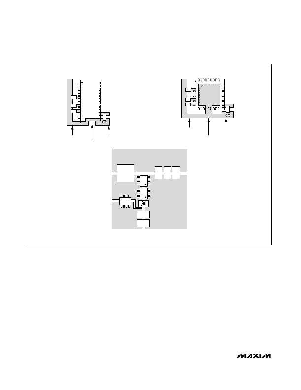
�QSOP� LAYOUT� EXAMPLE�
�CC�
�V� CC�
�QFN� LAYOUT� EXAMPLE�
�REF�
�V� DD�
�ANALOG�
�GROUND�
�POWER�
�GROUND�
�ANALOG�
�GROUND�
�POWER�
�GROUND�
�CONNECT� AGND�
�AND� PGND� TO� THE�
�CONNECT� AGND�
�AND� PGND� TO� THE�
�CONTROLLER� AT�
�ONE� POINT� ONLY�
�CONTROLLER� AT�
�ONE� POINT� ONLY�
�AS� SHOWN�
�OUTPUT�
�AS� SHOWN�
�INPUT�
�C� IN�
�GROUND�
�C� IN�
�POWER� STAGE� LAYOUT� EXAMPLE�
�Figure� 12.� PC� Board� Layout� Example�
�PC� Board� Layout� Guidelines�
�Careful� PC� board� layout� is� critical� to� achieving� low�
�switching� losses� and� clean,� stable� operation.� The�
�switching� power� stage� requires� particular� attention�
�(Figure� 12).� If� possible,� mount� all� of� the� power� compo-�
�nents� on� the� top� side� of� the� board,� with� their� ground�
�terminals� flush� against� one� another.� Follow� these� guide-�
�lines� for� good� PC� board� layout:�
�?� Keep� the� high-current� paths� short,� especially� at� the�
�ground� terminals.� This� practice� is� essential� for� sta-�
�ble,� jitter-free� operation.�
�?� Keep� the� power� traces� and� load� connections� short.�
�This� practice� is� essential� for� high� efficiency.� Using�
�thick� copper� PC� boards� (2oz� vs.� 1oz)� can� enhance�
�full-load� efficiency� by� 1%� or� more.� Correctly� routing�
�PC� board� traces� is� a� difficult� task� that� must� be�
�approached� in� terms� of� fractions� of� centimeters,�
�where� a� single� milliohm� of� excess� trace� resistance�
�causes� a� measurable� efficiency� penalty.�
�?� When� trade-offs� in� trace� lengths� must� be� made,� it� is�
�preferable� to� allow� the� inductor� charging� path� to� be�
�made� longer� than� the� discharge� path.� For� example,�
�it� is� better� to� allow� some� extra� distance� between� the�
�input� capacitors� and� the� high-side� MOSFET� than� to�
�allow� distance� between� the� inductor� and� the� low-�
�side� MOSFET� or� between� the� inductor� and� the� out-�
�put� filter� capacitor.�
�?� Route� high-speed� switching� nodes� (BST,� LX,� DH,� and�
�DL)� away� from� sensitive� analog� areas� (REF,� FB).�
�28�
�______________________________________________________________________________________�
�相关PDF资料 |
PDF描述 |
|---|---|
| RCC40DRAS | CONN EDGECARD 80POS R/A .100 SLD |
| MAX8720ETX+T | IC CNTRL VID STP DWN 36-TQFN |
| MAX17482GTL+T | IC CTLR PWM DUAL IMVP-6.5 40TQFN |
| 200MXG2200MEFCSN35X45 | CAP ALUM 2200UF 200V 20% SNAP-IN |
| MAX17082GTL+T | IC CTLR PWM DUAL IMVP-6.5 40TQFN |
相关代理商/技术参数 |
参数描述 |
|---|---|
| MAX8720ETX | 功能描述:DC/DC 开关控制器 RoHS:否 制造商:Texas Instruments 输入电压:6 V to 100 V 开关频率: 输出电压:1.215 V to 80 V 输出电流:3.5 A 输出端数量:1 最大工作温度:+ 125 C 安装风格: 封装 / 箱体:CPAK |
| MAX8720ETX+ | 功能描述:DC/DC 开关控制器 Dyn Adj 6-Bit VID Step-Down Controller RoHS:否 制造商:Texas Instruments 输入电压:6 V to 100 V 开关频率: 输出电压:1.215 V to 80 V 输出电流:3.5 A 输出端数量:1 最大工作温度:+ 125 C 安装风格: 封装 / 箱体:CPAK |
| MAX8720ETX+T | 功能描述:DC/DC 开关控制器 Dyn Adj 6-Bit VID Step-Down Controller RoHS:否 制造商:Texas Instruments 输入电压:6 V to 100 V 开关频率: 输出电压:1.215 V to 80 V 输出电流:3.5 A 输出端数量:1 最大工作温度:+ 125 C 安装风格: 封装 / 箱体:CPAK |
| MAX8720ETX-T | 功能描述:DC/DC 开关控制器 RoHS:否 制造商:Texas Instruments 输入电压:6 V to 100 V 开关频率: 输出电压:1.215 V to 80 V 输出电流:3.5 A 输出端数量:1 最大工作温度:+ 125 C 安装风格: 封装 / 箱体:CPAK |
| MAX8720EVKIT | 功能描述:DC/DC 开关控制器 Evaluation Kit for the MAX8720 RoHS:否 制造商:Texas Instruments 输入电压:6 V to 100 V 开关频率: 输出电压:1.215 V to 80 V 输出电流:3.5 A 输出端数量:1 最大工作温度:+ 125 C 安装风格: 封装 / 箱体:CPAK |
发布紧急采购,3分钟左右您将得到回复。