- 您现在的位置:买卖IC网 > PDF目录10341 > MAX9792CETI+ (Maxim Integrated Products)IC AMP AUDIO 2.0W STER D 28TQFN PDF资料下载
参数资料
| 型号: | MAX9792CETI+ |
| 厂商: | Maxim Integrated Products |
| 文件页数: | 10/34页 |
| 文件大小: | 0K |
| 描述: | IC AMP AUDIO 2.0W STER D 28TQFN |
| 产品培训模块: | Lead (SnPb) Finish for COTS Obsolescence Mitigation Program |
| 标准包装: | 1 |
| 系列: | DirectDrive® |
| 类型: | D 类 |
| 输出类型: | 1-通道(单声道),带立体声耳机 |
| 在某负载时最大输出功率 x 通道数量: | 3.7W x 1 @ 3 欧姆; 180mW x 2 @ 32 欧姆 |
| 电源电压: | 4.5 V ~ 5.5 V |
| 特点: | 消除爆音,LDO,短路保护和热保护,关机 |
| 安装类型: | 表面贴装 |
| 供应商设备封装: | 28-TQFN-EP(4x4) |
| 封装/外壳: | 28-WFQFN 裸露焊盘 |
| 包装: | 管件 |
第1页第2页第3页第4页第5页第6页第7页第8页第9页当前第10页第11页第12页第13页第14页第15页第16页第17页第18页第19页第20页第21页第22页第23页第24页第25页第26页第27页第28页第29页第30页第31页第32页第33页第34页
MAX9791/MAX9792
Windows Vista-Compliant Class D Speaker
Amplifiers with DirectDrive Headphone Amplifiers
18
______________________________________________________________________________________
Detailed Description
The MAX9791 combines a stereo 2W Class D power
amplifier, a stereo 175mW DirectDrive headphone
amplifier, and a 120mA LDO linear regulator in a single
device. The MAX9792 combines a mono 3W Class D
power amplifier, a stereo 175mW DirectDrive head-
phone amplifier, and a 120mA LDO linear regulator in a
single device.
The MAX9791/MAX9792 feature wake-on-beep detec-
tion, comprehensive click-and-pop suppression, low-
power shutdown mode, and excellent RF immunity.
These devices incorporate an integrated LDO that
serves as a clean power supply for CODEC or other cir-
cuits. The MAX9791/MAX9792 are Windows Vista
Premium compliant. See Table 1 for a comparison of the
Windows Vista Premium specifications and MAX9791/
MAX9792 specifications.
The MAX9791/MAX9792 feature spread-spectrum mod-
ulation and active emission limiting circuitry that offers
significant improvements to switch-mode amplifier tech-
nology. These devices offer Class AB performance with
Class D efficiency in a minimal board-space solution.
The headphone amplifiers use Maxim’s DirectDrive
architecture to eliminate the bulky output DC-blocking
capacitors required by traditional headphone ampli-
fiers. A charge pump inverts the positive supply
(HPVDD) to create a negative supply (CPVSS). The
headphone amplifiers operate from these bipolar sup-
plies with their outputs biased about GND. The bene-
fit of the GND bias is that the amplifier outputs no
longer have a DC component (typically VDD/2). This
feature eliminates the large DC-blocking capacitors
required with conventional headphone amplifiers to
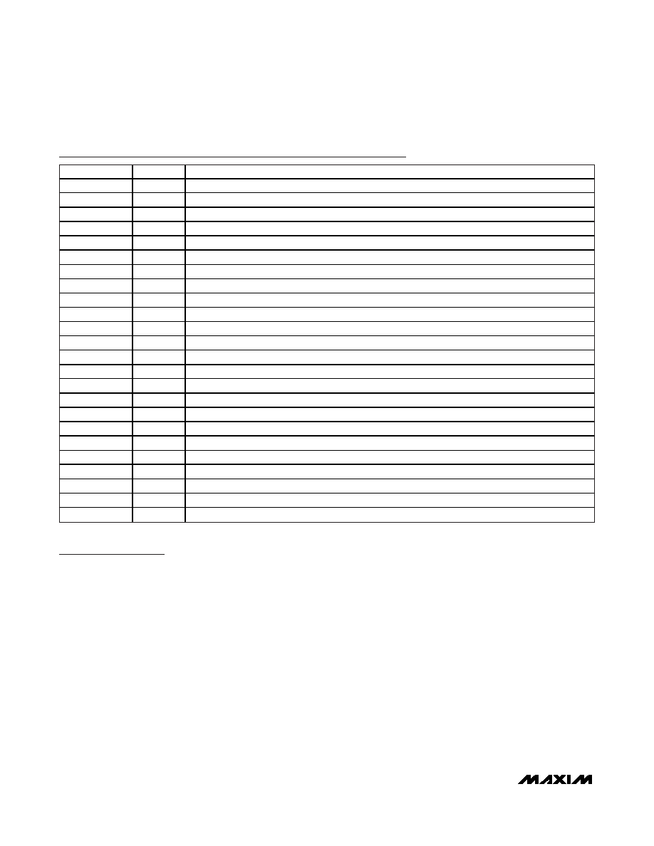
MAX9792 Pin Description
PIN
NAME
FUNCTION
1, 5
GND
Signal Ground. Star connect to PGND.
2
HP_INR
Right-Channel Headphone Amplifier Input
3
HP_INL
Left-Channel Headphone Amplifier Input
4
COM
Common-Mode Voltage Sense Input
6
LDO_OUT
LDO Output. Bypass with two 1F ceramic low ESR capacitors to GND.
7
AVDD
Positive Power Supply and LDO Input. Bypass with a 0.1F and two 1F capacitors to GND.
8
LDO_EN
LDO Enable. Connect LDO_EN to AVDD to enable the LDO.
9
HPR
Right-Channel Headphone Amplifier Output
10
HPL
Left-Channel Headphone Amplifier Output
11
SENSE
Headphone Ground Sense
12
CPVSS
Headphone Amplifier Negative Power Supply. Connect a 1F capacitor between CPVSS and PGND.
13
C1N
Charge-Pump Flying Capacitor Negative Terminal. Connect a 1F capacitor between C1P and C1N.
14
CPGND
Charge-Pump Ground. Connect directly to PGND plane.
15
C1P
Charge-Pump Flying Capacitor Positive Terminal. Connect a 1F capacitor between C1P and C1N.
16
HPVDD
Headphone Amplifier Positive Power Supply. Connect a 10F capacitor between HPVDD and PGND.
17, 26
PVDD
Speaker Amplifier Power-Supply Input. Bypass with a 0.1F capacitor to PGND.
18, 25
OUT-
Speaker Amplifier Output, Negative Phase
19, 24
OUT+
Speaker Amplifier Output, Positive Phase
20, 23
PGND
Power Ground. Star connect to GND.
21
BEEP
PC Beep Input. Connect to GND if beep detection function is disabled.
22
HP_EN
Active-High Headphone Amplifier Enable
27
SPKR_EN
Active-Low Speaker Amplifier Enable
28
SPKR_IN
Speaker Amplifier Input
—
EP
Exposed Pad. Connect to GND.
相关PDF资料 |
PDF描述 |
|---|---|
| MS27505E11F35SA | CONN RCPT 13POS BOX MNT W/SCKT |
| D38999/26WD97BN | CONN HSG PLUG 12POS STRGHT SCKT |
| LTC1096LCS8#TR | IC ADC 8BIT SERIAL I/O 3V 8SOIC |
| MS3101F10SL-4P | CONN RCPT 2POS FREE HNG W/PINS |
| LTC1199LIMS8 | IC ADC 10BIT 210KHZ W/SD 8-MSOP |
相关代理商/技术参数 |
参数描述 |
|---|---|
| MAX9792CETI+ | 功能描述:音频放大器 Windows Vista Class D Speaker Amp RoHS:否 制造商:STMicroelectronics 产品:General Purpose Audio Amplifiers 输出类型:Digital 输出功率: THD + 噪声: 工作电源电压:3.3 V 电源电流: 最大功率耗散: 最大工作温度: 安装风格:SMD/SMT 封装 / 箱体:TQFP-64 封装:Reel |
| MAX9792CETI+T | 功能描述:音频放大器 Windows Vista Class D Speaker Amp RoHS:否 制造商:STMicroelectronics 产品:General Purpose Audio Amplifiers 输出类型:Digital 输出功率: THD + 噪声: 工作电源电压:3.3 V 电源电流: 最大功率耗散: 最大工作温度: 安装风格:SMD/SMT 封装 / 箱体:TQFP-64 封装:Reel |
| MAX9796EBX+TG45 | 功能描述:音频放大器 2.3W High-Power Class D Subsystem RoHS:否 制造商:STMicroelectronics 产品:General Purpose Audio Amplifiers 输出类型:Digital 输出功率: THD + 噪声: 工作电源电压:3.3 V 电源电流: 最大功率耗散: 最大工作温度: 安装风格:SMD/SMT 封装 / 箱体:TQFP-64 封装:Reel |
| MAX9796EVKIT | 制造商:Maxim Integrated Products 功能描述:2.3W HIGH-POWER CLASS D AUDIO SUBS - Rail/Tube |
| MAX9796EVKIT+ | 制造商:Maxim Integrated Products 功能描述:MAX9796 EVAL KIT - Boxed Product (Development Kits) |
发布紧急采购,3分钟左右您将得到回复。