- 您现在的位置:买卖IC网 > PDF目录296470 > MAX9851EVCMODU (MAXIM INTEGRATED PRODUCTS INC) MAX9851评估板/评估系统 PDF资料下载
参数资料
| 型号: | MAX9851EVCMODU |
| 厂商: | MAXIM INTEGRATED PRODUCTS INC |
| 元件分类: | 编解码器 |
| 英文描述: | MAX9851评估板/评估系统 |
| 中文描述: | PCM CODEC |
| 文件页数: | 24/73页 |
| 文件大小: | 1357K |
| 代理商: | MAX9851EVCMODU |
第1页第2页第3页第4页第5页第6页第7页第8页第9页第10页第11页第12页第13页第14页第15页第16页第17页第18页第19页第20页第21页第22页第23页当前第24页第25页第26页第27页第28页第29页第30页第31页第32页第33页第34页第35页第36页第37页第38页第39页第40页第41页第42页第43页第44页第45页第46页第47页第48页第49页第50页第51页第52页第53页第54页第55页第56页第57页第58页第59页第60页第61页第62页第63页第64页第65页第66页第67页第68页第69页第70页第71页第72页第73页
MAX9851/MAX9853
Stereo Audio CODECs with Microphone, DirectDrive
Headphones, Speaker Amplifiers, or Line Outputs
30
______________________________________________________________________________________
Stereo Audio Modes
Set S1MAS or S2MAS to 1 (register 0x04 or 0x06, bit B7)
to operate the respective interface in master mode. The
MAX9851/MAX9853 generate the LRCLK and BCLK sig-
nals, which can be used to send and receive digital
audio samples. In stereo audio mode, the BCLK signal is
a pulse with a period of 310ns. BCLK is inactive when
there are no bits transmitted on SDIN or SDOUT. The
number of clock cycles per frame is equal to the config-
ured bit depth. Set S1MAS or S2MAS to 0 to operate the
respective interface in slave mode, and disable the ADC
in stereo audio modes (slave mode not available). The
interface accepts slave mode noninteger sample clocks
ranging from 8kHz to 48kHz and the appropriate bit
clocks in these DAC-only stereo audio modes. See
Figure 4 for the digital audio interface timing diagrams.
Voice Modes
In master voice mode, the S1 digital audio interface
operates as shown in Figure 3. The BCLK signal is a
continuous 13MHz clock. The LRCLK consists of a sin-
gle-pulse frame sync signal rather than the left-/
right-frame sync clock method used in I2S. Although
the 8kHz voice mode can be run from either the 13MHz
or 26MHz MCLK frequency, 16kHz voice mode
requires a 26MHz MCLK. Although both S1 and S2
interfaces are capable of operating in voice mode, only
the primary S1 interface can be configured with a
bandpass voice filter.
In slave voice mode, an external device must provide
at least 16 BCLK cycles following an LRCLK pulse,
which will allow operation using any BCLK rate or oper-
ation with BCLK shut off between word transfers.
In voice mode, the first 16 bits of each sample treated
as
left-channel
audio
data.
The
MAX9851/
MAX9853 are capable of receiving up to 16 additional
bits per sample word, treated as right-channel data.
These additional bits are routed to the Vibe circuitry
when operating in voice mode on the S1 interface.
When operating on the S2 interface, these additional
bits are interpreted as right-channel data, optionally
routed to the right DAC and the Vibe circuitry.
Additional Features
Included in each digital audio interface is a timing con-
trol module allowing the MAX9851/MAX9853 to gener-
ate the clock signals for master mode.
The two digital audio interfaces include full functionality
for I2S modes of operation, including true I2S data, left-
justified data, and either inverted LRCLK or inverted
BCLK. Set S1MODE or S2MODE to 0xA or 0xB (register
0x03 or 0x05, bits B3–B0) to configure the interface for
8kHz or 16kHz voice mode, respectively.
Set S1MNO or S2MNO to 1 (register 0x03 or 0x05, bit
B5) to mix the right- and left-channel input data to cre-
ate a mono serial data signal from the left and right
input data. The result is then input to the left digital filter
path, leaving the right path unused. The output of the
left filter path can still be sent to either or both the left
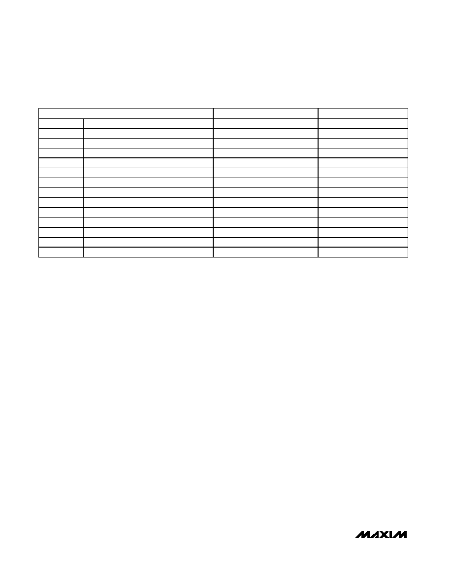
Table 1. Digital Audio Interface Modes
*26MHz clock required for synchronous 16kHz sample rate.
MODE
fS (ADC ON) (kHz)
fS (ADC OFF) (kHz)
48
Master (stereo audio mode)
47.794
48.0011
44.1
Master (stereo audio mode)
43.333
44.0989
32
Master (stereo audio mode)
31.863
31.9986
24
Master (stereo audio mode)
24.074
23.9990
22.05
Master (stereo audio mode)
21.959
22.0494
16
Master (stereo audio mode)
15.931
15.9993
12
Master (stereo audio mode)
12.037
12.0010
11.025
Master (stereo audio mode)
11.054
11.0247
8
Master (stereo audio mode)
8.025
7.9997
8
Master (voice mode)
8.000
16
Master (voice mode)
16.000*
8 to 48
Slave (stereo audio mode)
—
8 to 48
16
Slave (voice mode)
16.000*
8
Slave (voice mode)
8.000
相关PDF资料 |
PDF描述 |
|---|---|
| MAX9934FART+T | SPECIALTY ANALOG CIRCUIT, PBGA6 |
| MAX9950FCCB | SPECIALTY ANALOG CIRCUIT, PQFP64 |
| MAX9966BGCCQ+D | Quad, Low-Power, 500Mbps ATE Driver/Comparator |
| MAXQ2000-QBX | Low-Power LCD Microcontroller |
| MAYK062DG | 6.2 V, 0.2 W, SILICON, UNIDIRECTIONAL VOLTAGE REGULATOR DIODE |
相关代理商/技术参数 |
参数描述 |
|---|---|
| MAX9851EVKIT | 功能描述:音频 IC 开发工具 Evaluation Kit/Evaluation System for the MAX9851 RoHS:否 制造商:Texas Instruments 产品:Evaluation Kits 类型:Audio Amplifiers 工具用于评估:TAS5614L 工作电源电压:12 V to 38 V |
| MAX9853ETM+ | 功能描述:接口—CODEC Stereo Audio CODEC w/DirectDrive Amp RoHS:否 制造商:Texas Instruments 类型: 分辨率: 转换速率:48 kSPs 接口类型:I2C ADC 数量:2 DAC 数量:4 工作电源电压:1.8 V, 2.1 V, 2.3 V to 5.5 V 最大工作温度:+ 85 C 安装风格:SMD/SMT 封装 / 箱体:DSBGA-81 封装:Reel |
| MAX9853ETM+T | 功能描述:接口—CODEC Stereo Audio CODEC w/DirectDrive Amp RoHS:否 制造商:Texas Instruments 类型: 分辨率: 转换速率:48 kSPs 接口类型:I2C ADC 数量:2 DAC 数量:4 工作电源电压:1.8 V, 2.1 V, 2.3 V to 5.5 V 最大工作温度:+ 85 C 安装风格:SMD/SMT 封装 / 箱体:DSBGA-81 封装:Reel |
| MAX9853EVCMODU | 功能描述:音频 IC 开发工具 Evaluation Kit/Evaluation System for the MAX9853 RoHS:否 制造商:Texas Instruments 产品:Evaluation Kits 类型:Audio Amplifiers 工具用于评估:TAS5614L 工作电源电压:12 V to 38 V |
| MAX9853EVKIT | 功能描述:音频 IC 开发工具 Evaluation Kit/Evaluation System for the MAX9853 RoHS:否 制造商:Texas Instruments 产品:Evaluation Kits 类型:Audio Amplifiers 工具用于评估:TAS5614L 工作电源电压:12 V to 38 V |
发布紧急采购,3分钟左右您将得到回复。