- 您现在的位置:买卖IC网 > Datasheet目录342 > MC34848EPR2 (Freescale Semiconductor)IC LED DVR BACKLIGHT 8CH 48QFN Datasheet资料下载
参数资料
| 型号: | MC34848EPR2 |
| 厂商: | Freescale Semiconductor |
| 文件页数: | 22/38页 |
| 文件大小: | 0K |
| 描述: | IC LED DVR BACKLIGHT 8CH 48QFN |
| 产品变化通告: | AMPD Product Discontinuation 12/Dec/2012 |
| 标准包装: | 2,000 |
| 恒定电流: | 是 |
| 恒定电压: | 是 |
| 拓扑: | PWM,升压(升压) |
| 输出数: | 8 |
| 内部驱动器: | 是 |
| 类型 - 主要: | 背光 |
| 频率: | 200kHz ~ 1.2MHz |
| 电源电压: | 2.6 V ~ 3.6 V |
| 输出电压: | 45V |
| 安装类型: | 表面贴装 |
| 封装/外壳: | 48-VFQFN 裸露焊盘 |
| 供应商设备封装: | 48-QFN-EP(7x7) |
| 包装: | 带卷 (TR) |
| 工作温度: | -40°C ~ 85°C |
第1页第2页第3页第4页第5页第6页第7页第8页第9页第10页第11页第12页第13页第14页第15页第16页第17页第18页第19页第20页第21页当前第22页第23页第24页第25页第26页第27页第28页第29页第30页第31页第32页第33页第34页第35页第36页第37页第38页
�� �
�
�FUNCTIONAL� DEVICE� OPERATION�
�FUNCTIONAL� INTERNAL� BLOCK� DESCRIPTION�
�FUNCTIONAL� DEVICE� OPERATION�
�BOOST�
�An� integrated� sense� circuit� is� used� to� sense� the� voltage� at�
�the� LED� current� driver� inputs� and� automatically� sets� the�
�output� voltage� to� the� minimum� voltage� needed� to� keep� all�
�LEDs� biased� with� the� required� current.� Care� has� been� taken�
�to� ensure� that� the� minimum� required� output� voltage� (also� the�
�minimum� VF� of� the� LEDs)� is� used� in� order� to� minimize� on-�
�chip� power� dissipation.� The� boost� frequency� is� programmed�
�in� the� setup� routine� (see� 'Configuration'� below)� from� 200� kHz�
�to� 1.2� MHz,� or� can� be� synchronized� to� an� input� signal� if�
�provided� at� the� SYNC_IN� pin.� If� SYNC_IN� is� connected� to�
�GND,� an� on-chip� oscillator� is� used� to� generate� the� boost�
�frequency� and� the� boost� frequency� is� output� on� the�
�SYNC_OUT� pin.�
�The� boost� converter� also� features� Over-current� Protection�
�(OCP).� The� OCP� operates� on� a� cycle� by� cycle� basis.�
�However,� if� the� OCP� condition� remains� for� more� than� 60� ms�
�then� the� boost� regulator� is� latched� off� and� GD� asserts� high� to�
�shutoff� the� Q-FET.� The� device� can� only� be� restarted� by�
�recycling� the� power� supply.�
�The� SLEW� pin� is� used� to� limit� the� slew� on� the� OUT_SW� pin�
�to� reduce� noise� and� avoid� EMI� problems.� If� the� slew� rate� is�
�reduced� too� much,� the� efficiency� of� the� device� will� reduce.�
�The� slew� rate� can� be� changed� by� tying� a� resistor� from� the�
�SLEW� pin� to� GND.�
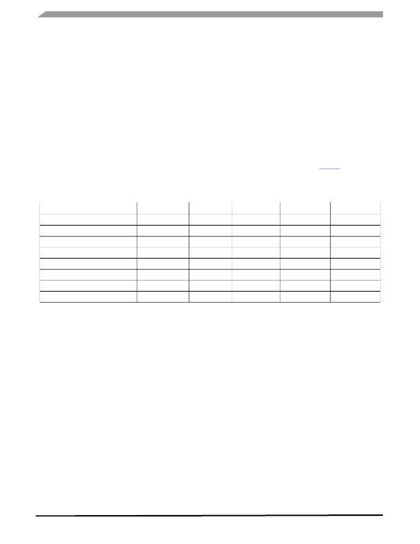
�The� Boost� converter� has� been� designed� to� operate� over� a�
�wide� range� of� switching� frequencies.� Table 9� shows� the�
�recommended� external� components� to� ensure� stable�
�operation� under� all� operating� conditions.�
�Table� 9.� Recommended� External� Components� (V� IN� =� 24� V� ±� 10%)�
�Switching� Frequency� [kHz]�
�200�
�300�
�400�
�500�
�600�
�700�
�900�
�1200�
�L� [� μ� H]�
�100�
�68�
�47�
�33�
�33�
�22�
�22�
�15�
�C� O� [� μ� F]�
�150�
�100�
�68�
�47�
�47�
�33�
�33�
�22�
�R� COMP� [k� ?� ]�
�130�
�130�
�130�
�130�
�130�
�130�
�130�
�130�
�C� COMP1� [nF]�
�1.5�
�1.0�
�0.7�
�0.6�
�0.5�
�0.4�
�0.3�
�0.2�
�C� COMP2� [pF]�
�59�
�39�
�29�
�24�
�20�
�-�
�-�
�-�
�The� output� capacitor� C� O� should� be� a� low� ESR� type,�
�preferably� a� MLCC.� If� an� electrolytic� capacitor� is� used,� a�
�small� value� ceramic� capacitor� should� be� connected� in� parallel�
�to� C� O� to� reduce� the� ESR,� thus� reducing� the� output� ripple�
�voltage� of� the� converter.�
�PWM� DIMMING�
�Each� channel� has� an� independently� programmable� 10-bit�
�PWM� generator.� The� data� for� the� PWM� generator� is�
�programmed� using� the� differential� interface� in� standard�
�operating� mode.� If� the� channel� is� programmed� with� 0� duty�
�cycle,� that� channel� is� programmed� off,� and� is� ignored� for�
�automatic� output� voltage� control� and� for� LED� failure� detection�
�(see� Protection� and� Diagnostic� Features� ).�
�The� PWM� generator� frequency� can� be� programmed� from�
�177� to� 1200� Hz� in� 1.0� Hz� step� using� a� register� in� the� start-up�
�control� registers,� and� is� generated� by� a� PLL� using� RESET-�
�SCAN� as� the� frequency� reference.� To� operate� in� Master�
�mode,� the� SYNC_IN� pin� is� connected� to� GND.� The� resulting�
�clock� for� PWM� pulse� generation� is� output� on� the� SYNC_PWM�
�pin.� A� compensation� network� is� connected� between� the�
�PLLC� pin� and� GND.� For� Slave� mode,� the� SYNC_PWM� pin�
�acts� as� an� input� for� the� reference� clock� for� the� PWM�
�generator.� In� this� manner,� one� device� can� be� used� as� the�
�master� IC,� SYNC_IN� tied� to� GND,� (compensation� network� on�
�PLLC,� and� SYNC_PWM� as� output)� and� the� remainder� as�
�slaves� (PLLC� grounded,� SYNC_PWM� as� input)� just� by�
�connecting� the� SYNC_PWM� pins� together.�
�The� default� Frame� Frequency� is� 120� Hz.� However,� the�
�RESET-SCAN� frequency� input� range� can� be� between� 80� and�
�180� Hz.� Therefore,� the� resulting� PWM� frequency� is� given� by�
�(F� RESET-SCAN� /120)� x� F� PWM� .�
�34848�
�Analog� Integrated� Circuit� Device� Data�
�22�
�Freescale� Semiconductor�
�相关PDF资料 |
PDF描述 |
|---|---|
| MC56F8006DEMO-T | BOARD DEMO FOR MC56F8006 DSP |
| MCB1114 | BOARD EVALUATION FOR NXP LPC1114 |
| MCB11C14 | BOARD EVAL FOR NXP LPC11C14 |
| MCB2470 | BOARD EVAL NXP LPC247X SERIES |
| MCBSTM32EXL | BOARD EVALUATION FOR STM32F103ZE |
相关代理商/技术参数 |
参数描述 |
|---|---|
| MC34849 | 制造商:SPC Multicomp 功能描述:HEADER VERTICAL 16WAY 制造商:SPC Multicomp 功能描述:WIRE-BOARD CONN, RECEPTACLE, 16POS, 3MM; Series:2261(5561); Pitch Spacing:3mm; Contact Termination:Through Hole Vertical; No. of Contacts:16; No. of Rows:2; Connector Mounting:PCB; Gender:Receptacle; Contact Material:Copper Alloy ;RoHS Compliant: Yes |
| MC34851 | 制造商:SPC Multicomp 功能描述:HEADER VERTICAL 18WAY 制造商:SPC Multicomp 功能描述:HEADER, VERTICAL, 18WAY |
| MC34853 | 制造商:SPC Multicomp 功能描述:HEADER R/ANGLE 16WAY 制造商:SPC Multicomp 功能描述:HEADER, R/ANGLE, 16WAY 制造商:SPC Multicomp 功能描述:WIRE-BOARD CONN, RECEPTACLE, 16POS, 3MM; Series:2261(5561); Pitch Spacing:3mm; Contact Termination:Through Hole Right Angle; No. of Contacts:16; No. of Rows:2; Connector Mounting:PCB; Gender:Receptacle; Contact Material:Copper Alloy ;RoHS Compliant: Yes |
| MC34855 | 制造商:SPC Multicomp 功能描述:HEADER R/ANGLE 18WAY 制造商:SPC Multicomp 功能描述:HEADER, R/ANGLE, 18WAY |
| MC34857 | 制造商:SPC Multicomp 功能描述:HEADER VERTICAL SMT 2WAY 制造商:SPC Multicomp 功能描述:HEADER, VERTICAL, SMT, 2WAY 制造商:SPC Multicomp 功能描述:WIRE-BOARD CONN, RECEPTACLE, 2POS, 3MM; Series:2261(5561)R; Pitch Spacing:3mm; Contact Termination:Surface Mount Vertical; No. of Contacts:2; No. of Rows:2; Connector Mounting:PCB; Gender:Receptacle; Contact Material:Copper Alloy ;RoHS Compliant: Yes |
发布紧急采购,3分钟左右您将得到回复。