- 您现在的位置:买卖IC网 > PDF目录45281 > MC908QL4MDWR2 (FREESCALE SEMICONDUCTOR INC) 8-BIT, FLASH, 8 MHz, MICROCONTROLLER, PDSO16 PDF资料下载
参数资料
| 型号: | MC908QL4MDWR2 |
| 厂商: | FREESCALE SEMICONDUCTOR INC |
| 元件分类: | 微控制器/微处理器 |
| 英文描述: | 8-BIT, FLASH, 8 MHz, MICROCONTROLLER, PDSO16 |
| 封装: | 1.27 MM PITCH, MS-013AA, SOIC-16 |
| 文件页数: | 77/226页 |
| 文件大小: | 2911K |
| 代理商: | MC908QL4MDWR2 |
第1页第2页第3页第4页第5页第6页第7页第8页第9页第10页第11页第12页第13页第14页第15页第16页第17页第18页第19页第20页第21页第22页第23页第24页第25页第26页第27页第28页第29页第30页第31页第32页第33页第34页第35页第36页第37页第38页第39页第40页第41页第42页第43页第44页第45页第46页第47页第48页第49页第50页第51页第52页第53页第54页第55页第56页第57页第58页第59页第60页第61页第62页第63页第64页第65页第66页第67页第68页第69页第70页第71页第72页第73页第74页第75页第76页当前第77页第78页第79页第80页第81页第82页第83页第84页第85页第86页第87页第88页第89页第90页第91页第92页第93页第94页第95页第96页第97页第98页第99页第100页第101页第102页第103页第104页第105页第106页第107页第108页第109页第110页第111页第112页第113页第114页第115页第116页第117页第118页第119页第120页第121页第122页第123页第124页第125页第126页第127页第128页第129页第130页第131页第132页第133页第134页第135页第136页第137页第138页第139页第140页第141页第142页第143页第144页第145页第146页第147页第148页第149页第150页第151页第152页第153页第154页第155页第156页第157页第158页第159页第160页第161页第162页第163页第164页第165页第166页第167页第168页第169页第170页第171页第172页第173页第174页第175页第176页第177页第178页第179页第180页第181页第182页第183页第184页第185页第186页第187页第188页第189页第190页第191页第192页第193页第194页第195页第196页第197页第198页第199页第200页第201页第202页第203页第204页第205页第206页第207页第208页第209页第210页第211页第212页第213页第214页第215页第216页第217页第218页第219页第220页第221页第222页第223页第224页第225页第226页
Slave LIN Interface Controller (SLIC) Module
MC68HC908QL4 Data Sheet, Rev. 7
168
Freescale Semiconductor
The error also comes into effect with transmitted bit times. Using the previous example with a SLCBT
value of 34, transmitted bits will appear as 34 SLIC clock periods long. This is one SLIC clock short of the
proper length. Depending on the frequency of the SLIC clock, one period of the SLIC clock might be a
large or a small fraction of one ideal bit time. Raising the frequency of the SLIC clock will reduce this error
relative to the ideal bit time, improving the resolution of the SLIC clock relative to the bit rate of the bus.
In any case, the error is still one SLIC clock cycle. Raising the SLIC clock frequency, however, requires
programming a higher value for SLCBT to maintain the same target bit rate.
Smaller values of SLCBT combined with higher values of the SLIC clock frequency (smaller clock period)
will give faster bit rates, but the SLIC clock period becomes an increasingly significant portion of one bit
time.
Because BTM mode does not perform any synchronization and relies on the accuracy of the data
provided by the user software to set its sample point and generate transmitted bits, the constraint on
maximum speeds is only limited to the limits imposed by the digital filter delay and the SLIC input clock.
Because the digital filter delay cannot be less than 16 SLIC clock cycles, the fastest possible pulse which
would pass the filter is 16 clock periods at 8 MHz, or 500,000 bits/second. The values shown in Table 14-7
are the same values shown in Table 14-8 and indicate the absolute fastest bit rates which could just pass
the minimum digital filter settings (prescaler = divide by 1) under perfect conditions.
Because perfect conditions are almost impossible to attain, more robust values must be chosen for bit
rates. For reliable communication, it is best to ensure that a bit time is no smaller 2x–3x longer than the
filter delay on the digital receive filter. This is true in LIN or BTM mode and ensures that valid data bits
which have been shortened due to ground shift, asymmetrical rise and fall times, etc., are accepted by
the filter without exception. This would translate to 2x to 3x reduction in the maximum speeds shown in
Table 14-7. Recommended maximum bit rates are shown in Table 14-8, and ensure that a single bit time
is at least twice the length of one filter delay value. If system noise is not adequately filtered out it might
be necessary to change the prescaler of the filter and lower the bit rate of the communication. If valid
communications are being absorbed by the filter, corrective action must be taken to ensure that either the
bit rate is reduced or whatever physical fault is causing bit times to shorten is corrected (ground offset,
asymmetrical rise/fall times, insufficient physical layer supply voltage, etc.).
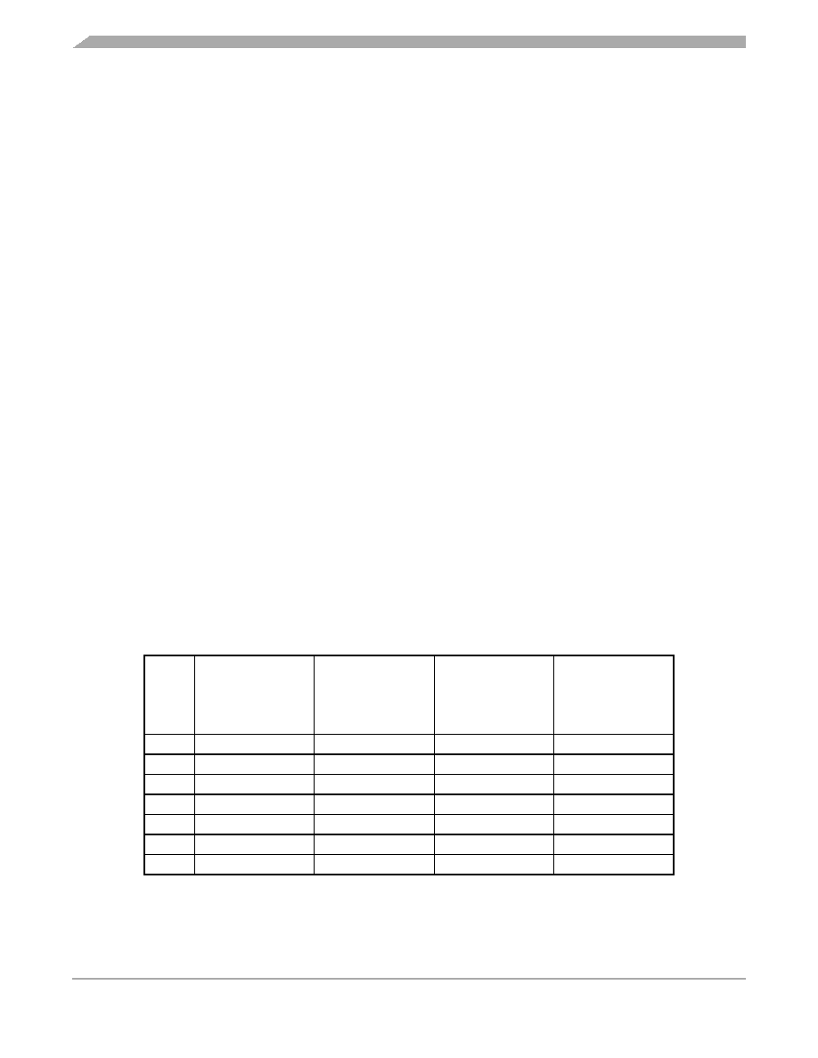
Table 14-8. Recommended Maximum Bit Rates
for BTM Operation Due to Digital Filter
SLIC
Clock
(MHz)
Maximum BTM
Bit Rate with
Digital RX Filter
Set to
÷4
(Bits / Second)
Maximum BTM
Bit Rate with
Digital RX Filter
Set to
÷3
(Bits / Second)
Maximum BTM
Bit Rate with
Digital RX Filter
Set to
÷2
(Bits / Second)
Maximum BTM
Bit Rate with
Digital RX Filter
Set to
÷1
(Bits / Second)
8
62,500
83,333
120,000(1)
1. Bit rates over 120,000 bits per second are not recommended for BTM communications, as
physical layer delay between the TX and RX pins can cause the stop bit of a byte to be
missampled as the last data bit. This could result in a byte framing error.
120,000(1)
6.4
50,000
66,667
100,000
120,000(1)
4.8
37,500
50,000
75,000
120,000(1)
4
31,250
41,667
62,500
120,000(1)
3.2
25,000
33,333
50,000
100,000
2.4
18,750
25,000
37,500
75,000
2
15,625
20,833
31,250
62,500
相关PDF资料 |
PDF描述 |
|---|---|
| MC908QL4MDW | 8-BIT, FLASH, 8 MHz, MICROCONTROLLER, PDSO16 |
| MC908QL4MDT | 8-BIT, FLASH, 8 MHz, MICROCONTROLLER, PDSO16 |
| MC908QT1MDWE | 8-BIT, FLASH, 8 MHz, MICROCONTROLLER, PDSO8 |
| MC908QY2CDWE | 8-BIT, FLASH, 8 MHz, MICROCONTROLLER, PDSO16 |
| MC908QT2VFQE | 8-BIT, FLASH, 8 MHz, MICROCONTROLLER, PDSO8 |
相关代理商/技术参数 |
参数描述 |
|---|---|
| MC908QL4V | 制造商:MOTOROLA 制造商全称:Motorola, Inc 功能描述:Microcontrollers |
| MC908QL4VDTE | 制造商:FREESCALE 制造商全称:Freescale Semiconductor, Inc 功能描述:M68HC08 Microcontrollers |
| MC908QL4VDWE | 制造商:FREESCALE 制造商全称:Freescale Semiconductor, Inc 功能描述:M68HC08 Microcontrollers |
| MC908QT1 | 制造商:FREESCALE 制造商全称:Freescale Semiconductor, Inc 功能描述:Microcontrollers |
| MC908QT1A | 制造商:FREESCALE 制造商全称:Freescale Semiconductor, Inc 功能描述:Microcontrollers |
发布紧急采购,3分钟左右您将得到回复。