- 您现在的位置:买卖IC网 > PDF目录15806 > MCP1318MT-29LE/OT (Microchip Technology)IC SUPERVISOR 2.9V OD/PP SOT23-5 PDF资料下载
参数资料
| 型号: | MCP1318MT-29LE/OT |
| 厂商: | Microchip Technology |
| 文件页数: | 34/52页 |
| 文件大小: | 0K |
| 描述: | IC SUPERVISOR 2.9V OD/PP SOT23-5 |
| 标准包装: | 3,000 |
| 类型: | 简单复位/加电复位 |
| 监视电压数目: | 1 |
| 输出: | 开路漏极,推挽式 |
| 复位: | 高有效/低有效 |
| 复位超时: | 最小为 140 ms |
| 电压 - 阀值: | 2.9V |
| 工作温度: | -40°C ~ 125°C |
| 安装类型: | 表面贴装 |
| 封装/外壳: | SC-74A,SOT-753 |
| 供应商设备封装: | SOT-23-5 |
| 包装: | 带卷 (TR) |
第1页第2页第3页第4页第5页第6页第7页第8页第9页第10页第11页第12页第13页第14页第15页第16页第17页第18页第19页第20页第21页第22页第23页第24页第25页第26页第27页第28页第29页第30页第31页第32页第33页当前第34页第35页第36页第37页第38页第39页第40页第41页第42页第43页第44页第45页第46页第47页第48页第49页第50页第51页第52页
�� �
�
�MCP131X/2X�
�4.5� Watchdog� Timer�
�The� purpose� of� the� Watchdog� Timer� (WDT)� is� to�
�increase� system� reliability.� The� Watchdog� Timer�
��MCP131X/2X� with� a� PIC� ?� microcontroller� (MCU)� and�
�the� Watchdog� input.�
�feature� can� be� used� to� detect� when� the� Host�
�Controller� ’s� program� flow� is� not� as� expected.� The�
�Watchdog� Timer� monitors� for� activity� on� the� Watchdog�
�TABLE� 4-3:�
�WATCHDOG� TIMER�
��Input� pin� (WDI).� The� WDI� pin� is� expected� to� be� strobed�
�within� a� given� time� frame.� When� this� time� frame� is�
�exceeded,� without� an� edge� transition� on� the� WDI� pin,�
�the� Reset� pin� is� driven� active� to� reset� the� system.� This�
�stops� the� Host� Controller� from� continuing� its� erratic�
�behavior� (“run-away”� code� execution).�
�The� Watchdog� Timer� is� external� to� the� main� portion� of�
�the� control� system� and� monitors� the� operation� of� the�
�system.� This� feature� is� enabled� by� a� falling� edge� on� the�
�WDI� pin� (after� device� POR).� Monitoring� is� then� done� by�
�requiring� the� embedded� controller� to� force� an� edge�
�transition� (falling� or� rising)� on� the� WDI� pin� (“pet� the�
�Watchdog”)� within� a� predetermined� time� frame� (T� WD� ).�
�If� the� MCP131X/2X� does� not� detect� an� edge� on� the�
�WDI� pin� within� the� expected� time� frame,� the�
�MCP131X/2X� device� will� force� the� Reset� pin� active.�
�Min�
�4.3�
�71�
�1.12�
�17.9�
�↑�
�If� the� time� between�
�WDI� edges� is� less�
�than� this,� it�
�ensures� that� the�
�MCP131X/2X�
�never� forces� a�
�reset�
�t� WDT�
�Typ�
�6.3�
�102�
�1.6�
�25.6�
�Max�
�9.3�
�153�
�2.4�
�38.4�
�↑�
�If� the� time�
�between� WDI�
�edges� is� greater�
�than� this,� it�
�ensures� that� the�
�MCP131X/2X�
�always� forces� a�
�Units�
�ms�
�ms�
�sec�
�sec�
�The� Watchdog� Timer� is� in� the� disabled� state� when:�
�reset�
�?�
�?�
�?�
�?�
�The� Device� Powers� up�
�A� POR� event� occurred�
�A� WDT� event� occurred�
�A� Manual� Reset� (MR)� event� occurred�
�Note� 1:�
�Shaded� rows� are� custom� ordered� Watch-�
�dog� Timer� Periods� (t� WDT� )� time� outs.� For�
�information� on� ordering� devices� with�
�these� t� WDT� time� outs,� please� contact� your�
�local� Microchip� sales� office.� Minimum�
�When� the� Watchdog� Timer� is� in� the� disabled� state,� the�
�WDI� pin� has� an� internal� smart� pull-up� resistor� enabled.�
�This� pull-up� resistor� has� a� typical� value� of� 52� k� Ω� .� This�
�purchase� volumes� are� required.�
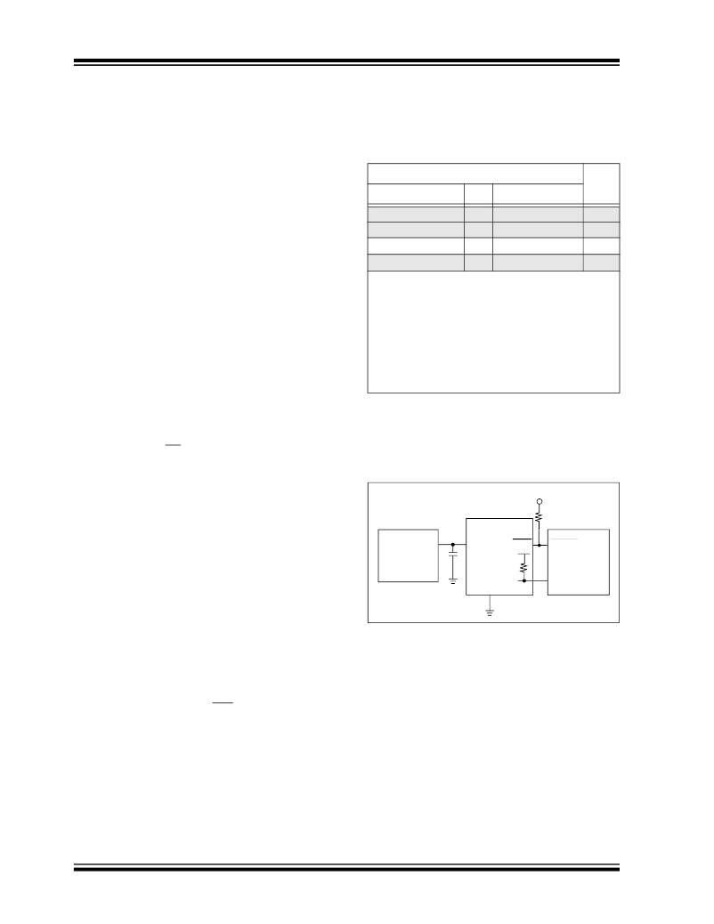
�+5V�
�pull-up� resistor� holds� the� WDI� signal� in� the� high� state,�
�until� it� is� forced� to� another� state.�
�MCP13XX�
�10� k� Ω�
�After� the� embedded� controller� has� initialized,� if� the�
�Watchdog� Timer� feature� is� to� be� used,� then� the� embed-�
�ded� controller� can� force� the� WDI� pin� low� (V� IL� ).� This� also�
�enables� the� Watchdog� Timer� feature� and� disables� the�
�3-Terminal�
�Regulator�
�(example:�
�MCP1700� )�
�+5V�
�0.1�
�μF�
�V� CC�
�RST�
�WDI�
�MCLR�
�PIC� ?�
�MCU�
�I/O�
�WDI� pull-up� resistor.� Disabling� the� pull-up� resistor�
�reduces� the� device’s� current� consumption.� The� pull-up�
�resistor� will� remain� disconnected� until� the� device� has� a�
�GND�
�power-on,� a� Reset� event� occurs,� or� after� the� WDT� time�
�FIGURE� 4-19:�
�Watchdog� Timer.�
�out.�
�Once� the� Watchdog� Timer� has� been� enabled,� the� Host�
�Controller� must� force� an� edge� transition� (falling� or� ris-�
�ing)� on� the� WDI� pin� before� the� minimum� Watchdog�
�Timer� time� out� to� ensure� that� the� Watchdog� Timer� does�
�not� force� the� Reset� pins� (RST/RST)� to� the� active� state.�
�If� an� edge� transition� does� not� occur� before� the� maxi-�
�mum� time� out� occurs,� then� the� MCP131X/2X� will� force�
�the� Reset� pins� to� their� active� state.�
�The� MCP131X/2X� supports� four� time� outs.� The� stan-�
�dard� offering� devices� have� a� typical� Watchdog� Timer�
�period� (T� WDT� )� of� 1.6� s.� Table� 4-3� shows� the� available�
�Watchdog� Timer� periods.� The� t� WDT� time� out� is� a�
�function� of� the� device� voltage� and� temperature.�
�DS21985C-page� 34�
�The� software� routine� that� strobes� WDI� is� critical.� The�
�code� must� be� in� a� section� of� software� that� is� executed�
�frequently� enough� so� the� time� between� edge�
�transitions� is� less� than� the� Watchdog� time� out� period.�
�One� common� technique� controls� the� Host� Controllers�
�I/O� line� from� two� sections� of� the� program.� The� software�
�might� set� the� I/O� line� high� while� operating� in� the�
�Foreground� mode� and� set� it� low� while� in� the�
�Background� or� Interrupt� modes.� If� both� modes� do� not�
�execute� correctly,� the� Watchdog� Timer� issues� reset�
�pulses.�
�?� 2005-2012� Microchip� Technology� Inc.�
�相关PDF资料 |
PDF描述 |
|---|---|
| V24C28E50BL2 | CONVERTER MOD DC/DC 28V 50W |
| ECA14DRMT | CONN EDGECARD 28POS .125 SQ WW |
| EYM12DTAD-S664 | CONN EDGECARD 24POS R/A .156 SLD |
| 1838355-4 | CONN FMALE M12 8POS STR 7M CABLE |
| EYM10DRSN-S664 | CONN EDGECARD 20POS DIP .156 SLD |
相关代理商/技术参数 |
参数描述 |
|---|---|
| MCP1318MT-46LE/OT | 功能描述:监控电路 Active high P-P RoHS:否 制造商:STMicroelectronics 监测电压数: 监测电压: 欠电压阈值: 过电压阈值: 输出类型:Active Low, Open Drain 人工复位:Resettable 监视器:No Watchdog 电池备用开关:No Backup 上电复位延迟(典型值):10 s 电源电压-最大:5.5 V 最大工作温度:+ 85 C 安装风格:SMD/SMT 封装 / 箱体:UDFN-6 封装:Reel |
| MCP1318T | 制造商:MICROCHIP 制造商全称:Microchip Technology 功能描述:Voltage Supervisor |
| MCP1318T-29HE/OT | 功能描述:监控电路 ACTIVE LOW/HIGH P-P WDI RoHS:否 制造商:STMicroelectronics 监测电压数: 监测电压: 欠电压阈值: 过电压阈值: 输出类型:Active Low, Open Drain 人工复位:Resettable 监视器:No Watchdog 电池备用开关:No Backup 上电复位延迟(典型值):10 s 电源电压-最大:5.5 V 最大工作温度:+ 85 C 安装风格:SMD/SMT 封装 / 箱体:UDFN-6 封装:Reel |
| MCP1318T-29LE/CH | 功能描述:监控电路 WDI Active Lo P-P Active HI P-P RoHS:否 制造商:STMicroelectronics 监测电压数: 监测电压: 欠电压阈值: 过电压阈值: 输出类型:Active Low, Open Drain 人工复位:Resettable 监视器:No Watchdog 电池备用开关:No Backup 上电复位延迟(典型值):10 s 电源电压-最大:5.5 V 最大工作温度:+ 85 C 安装风格:SMD/SMT 封装 / 箱体:UDFN-6 封装:Reel |
| MCP1318T-29LE/OT | 功能描述:监控电路 Active low P-P RoHS:否 制造商:STMicroelectronics 监测电压数: 监测电压: 欠电压阈值: 过电压阈值: 输出类型:Active Low, Open Drain 人工复位:Resettable 监视器:No Watchdog 电池备用开关:No Backup 上电复位延迟(典型值):10 s 电源电压-最大:5.5 V 最大工作温度:+ 85 C 安装风格:SMD/SMT 封装 / 箱体:UDFN-6 封装:Reel |
发布紧急采购,3分钟左右您将得到回复。