- 您现在的位置:买卖IC网 > PDF目录17188 > MCP1631RD-DCPC1 (Microchip Technology)REF DES BATT CHARG OR LED DRIVER PDF资料下载
参数资料
| 型号: | MCP1631RD-DCPC1 |
| 厂商: | Microchip Technology |
| 文件页数: | 10/44页 |
| 文件大小: | 0K |
| 描述: | REF DES BATT CHARG OR LED DRIVER |
| 标准包装: | 1 |
| 电流 - 输出 / 通道: | 700mA |
| 输出及类型: | 1,非隔离 |
| 特点: | 用于锂离子、镍氢和镍镉电池充电器的固件 |
| 输入电压: | 3.5 ~ 16 V |
| 已供物品: | 板 |
| 已用 IC / 零件: | MCP1631HV,PIC16F616 |
| 产品目录页面: | 668 (CN2011-ZH PDF) |
| 相关产品: | MCP1631HV-500E/SS-ND - IC REG CTRLR ISO PWM CM 20-SSOP MCP1631HV-330E/ST-ND - IC REG CTRLR ISO PWM CM 20-TSSOP MCP1631HV-330E/SS-ND - IC REG CTRLR ISO PWM CM 20-SSOP MCP1631HV-500E/ST-ND - IC REG CTRLR ISO PWM CM 20-TSSOP MCP1631HVT-330E/SSTR-ND - IC REG CTRLR ISO PWM CM 20-SSOP MCP1631HVT-500E/SSTR-ND - IC REG CTRLR ISO PWM CM 20-SSOP MCP1631HVT-500E/STTR-ND - IC REG CTRLR ISO PWM CM 20-TSSOP MCP1631HVT-330E/STTR-ND - IC REG CTRLR ISO PWM CM 20-TSSOP PIC16F616T-I/ML-ND - IC PIC MCU FLASH 2KX14 16QFN PIC16F616T-I/ST-ND - IC PIC MCU FLASH 2KX14 14TSSOP 更多... |
第1页第2页第3页第4页第5页第6页第7页第8页第9页当前第10页第11页第12页第13页第14页第15页第16页第17页第18页第19页第20页第21页第22页第23页第24页第25页第26页第27页第28页第29页第30页第31页第32页第33页第34页第35页第36页第37页第38页第39页第40页第41页第42页第43页第44页
PIC16F610/616/16HV610/616
DS41288F-page 18
2009 Microchip Technology Inc.
2.2.2.1
STATUS Register
The STATUS register, shown in Register 2-1, contains:
the arithmetic status of the ALU
the Reset status
the bank select bits for data memory (RAM)
The STATUS register can be the destination for any
instruction, like any other register. If the STATUS
register is the destination for an instruction that affects
the Z, DC or C bits, then the write to these three bits is
disabled. These bits are set or cleared according to the
device logic. Furthermore, the TO and PD bits are not
writable. Therefore, the result of an instruction with the
STATUS register as destination may be different than
intended.
For example, CLRF STATUS, will clear the upper three
bits and set the Z bit. This leaves the STATUS register
as ‘000u u1uu’ (where u = unchanged).
It is recommended, therefore, that only BCF, BSF,
SWAPF
and MOVWF instructions are used to alter the
STATUS register, because these instructions do not
affect any Status bits. For other instructions not affect-
ing any Status bits, see the Section 13.0 “Instruction
Note 1: Bits IRP and RP1 of the STATUS register
are
not
used
by
the
PIC16F610/616/16HV610/616
and
should be maintained as clear. Use of
these bits is not recommended, since this
may affect upward compatibility with
future products.
2: The C and DC bits operate as a Borrow
and Digit Borrow out bit, respectively, in
subtraction. See the SUBLW and SUBWF
instructions for examples.
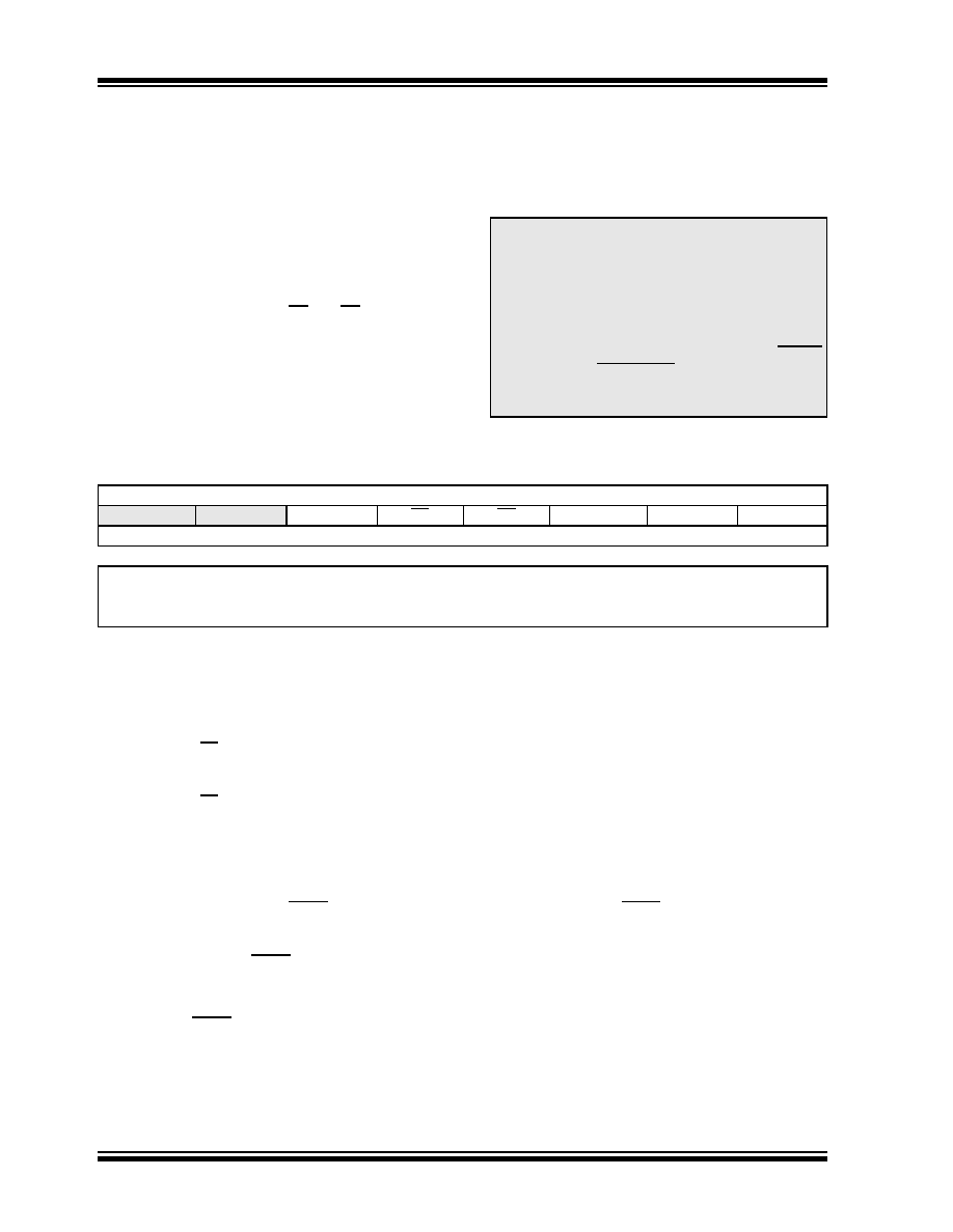
REGISTER 2-1:
STATUS: STATUS REGISTER
Reserved
R/W-0
R-1
R/W-x
IRP
RP1
RP0
TO
PD
ZDC
C
bit 7
bit 0
Legend:
R = Readable bit
W = Writable bit
U = Unimplemented bit, read as ‘0’
-n = Value at POR
‘1’ = Bit is set
‘0’ = Bit is cleared
x = Bit is unknown
bit 7
IRP: This bit is reserved and should be maintained as ‘0’
bit 6
RP1: This bit is reserved and should be maintained as ‘0’
bit 5
RP0: Register Bank Select bit (used for direct addressing)
1
= Bank 1 (80h – FFh)
0
= Bank 0 (00h – 7Fh)
bit 4
TO: Time-out bit
1
= After power-up, CLRWDT instruction or SLEEP instruction
0
= A WDT time-out occurred
bit 3
PD: Power-down bit
1
= After power-up or by the CLRWDT instruction
0
= By execution of the SLEEP instruction
bit 2
Z: Zero bit
1
= The result of an arithmetic or logic operation is zero
0
= The result of an arithmetic or logic operation is not zero
bit 1
DC: Digit Carry/Borrow bit (ADDWF, ADDLW,SUBLW,SUBWF instructions), For Borrow, the polarity is reversed.
1
= A carry-out from the 4th low-order bit of the result occurred
0
= No carry-out from the 4th low-order bit of the result
bit 0
C: Carry/Borrow bit(1) (ADDWF, ADDLW, SUBLW, SUBWF instructions)
1
= A carry-out from the Most Significant bit of the result occurred
0
= No carry-out from the Most Significant bit of the result occurred
Note
1:
For Borrow, the polarity is reversed. A subtraction is executed by adding the two’s complement of the second operand.
For rotate (RRF, RLF) instructions, this bit is loaded with either the high-order or low-order bit of the source register.
相关PDF资料 |
PDF描述 |
|---|---|
| GEC30DRXN | CONN EDGECARD 60POS DIP .100 SLD |
| TC4467CPD | IC MOSFET DVR QUAD NAND 14DIP |
| TC1411VUA713 | IC MOSFET DVR 1A HS INV 8MSOP |
| R1D-1209/P | CONV DC/DC 1W 12VIN +/-09VOUT |
| T95S335K016CZAL | CAP TANT 3.3UF 16V 10% 1507 |
相关代理商/技术参数 |
参数描述 |
|---|---|
| MCP1631RD-MCC1 | 功能描述:电源管理IC开发工具 MCP1631HV Multi-Chem Chrgr Ref Design RoHS:否 制造商:Maxim Integrated 产品:Evaluation Kits 类型:Battery Management 工具用于评估:MAX17710GB 输入电压: 输出电压:1.8 V |
| MCP1631RD-MCC2 | 功能描述:开关变换器、稳压器与控制器 MCP1631HV Multi-Chem BuckBst Chg Ref Dsgn RoHS:否 制造商:Texas Instruments 输出电压:1.2 V to 10 V 输出电流:300 mA 输出功率: 输入电压:3 V to 17 V 开关频率:1 MHz 工作温度范围: 安装风格:SMD/SMT 封装 / 箱体:WSON-8 封装:Reel |
| MCP1631T | 制造商:MICROCHIP 制造商全称:Microchip Technology 功能描述:High-Speed, Pulse Width Modulator |
| MCP1631T-330E/ML | 制造商:MICROCHIP 制造商全称:Microchip Technology 功能描述:High-Speed, Pulse Width Modulator |
| MCP1631T-330E/SS | 制造商:MICROCHIP 制造商全称:Microchip Technology 功能描述:High-Speed, Pulse Width Modulator |
发布紧急采购,3分钟左右您将得到回复。