- 您现在的位置:买卖IC网 > PDF目录67986 > MCP25025-I/P SPECIALTY MICROPROCESSOR CIRCUIT, PDIP14 PDF资料下载
参数资料
| 型号: | MCP25025-I/P |
| 元件分类: | 微控制器/微处理器 |
| 英文描述: | SPECIALTY MICROPROCESSOR CIRCUIT, PDIP14 |
| 封装: | 0.300 INCH, PLASTIC, DIP-14 |
| 文件页数: | 20/64页 |
| 文件大小: | 1232K |
| 代理商: | MCP25025-I/P |
第1页第2页第3页第4页第5页第6页第7页第8页第9页第10页第11页第12页第13页第14页第15页第16页第17页第18页第19页当前第20页第21页第22页第23页第24页第25页第26页第27页第28页第29页第30页第31页第32页第33页第34页第35页第36页第37页第38页第39页第40页第41页第42页第43页第44页第45页第46页第47页第48页第49页第50页第51页第52页第53页第54页第55页第56页第57页第58页第59页第60页第61页第62页第63页第64页
2003 Microchip Technology Inc.
DS21664C-page 27
MCP2502X/5X
4.5
Automatic Transmission
The MCP2502X/5X can automatically initiate four
different message types to indicate the following
situations:
Edge detected on a digital input (TXID2).
Threshold exceeded on an analog input (TXID2).
Error condition (Read Error output message).
Scheduled transmissions (TXID0).
The buffers have an implied transmit priority, where
buffer 2 is the highest and buffer 0 is the lowest.
Therefore, multiple message buffers can be requested
for transmission and each one will be sent in order of
priority.
4.5.1
DIGITAL INPUT EDGE DETECTION
Each GPIO pin configured as a digital input can be
individually configured to automatically transmit a
message when a defined edge occurs, as explained in
the GPIO module section. When transmitting this
message, the MCP2502X/5X uses TXID2. The DLC is
set to two and the first two bytes of the Read A/D
registers (IOINTFL and GPIO) are sent.
4.5.2
ANALOG INPUT THRESHOLD
DETECTION
Each GPIO pin that has been configured as an analog
input can be individually configured to automatically
transmit a message when a threshold is exceeded as
described in the Analog-to-Digital Converter Module
section. The MCP2502X/5X sends TXID2 when
transmitting this message. The DLC is set to eight and
the eight bytes of the ‘Read A/D Registers’ are sent.
4.5.2.1
Hysteresis Function
This function is automatic and will insure that an analog
value that is on the compare edge (i.e., toggling LSb)
does not fill the CAN bus with continuous A/D message
transmissions.
The hysteresis uses the two LSb’s of the compare
register. These two bits are forced and are not
configurable by the user. They will be forced to either
b’00’
or b’11’, depending on the compare polarity. If
configured for A/D result > compare register, the
automatic transmission will occur when the A/D value
is greater than or equal to b’nnnn nnnn 11’ and
reset when less than or equal to b’nnnn nnnn 00’.
The opposite conditions must occur if the compare
polarity is set for A/D result < compare register.
A hysteresis example:
The user sets the upper-eight bits of the 10-bit
compare register (ADCMP0H). The lower-two bits
of the compare register are not configurable by
the user and are forced to either b’11’ or b’00’
depending on the polarity of the compare
threshold (i.e., transmit is triggered above or
below the compare value via the IOINTPO
register).
The user sets the polarity of the compare
threshold (IOINTPO). In this example, the
threshold is set for triggering a message on an
A/D > compare register. The two LSb’s are forced
to b’11’.
When the A/D conversion exceeds the compare
register (b’nnnn nnnn 11’), an automatic
transmission will occur once.
In order for the automatic transmission to occur
again, the A/D value must first drop below the
compare register b’nnnn nnnn 00’ and then
back above the compare register
b’nnnn nnnn 11’
.
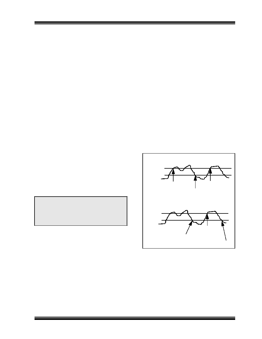
FIGURE 4-1:
HYSTERESIS
FUNCTION
4.5.3
ERROR CONDITION
The MCP2502X/5X can be configured to automatically
transmit a message whenever one or more of the
following error conditions occur:
Receiver has entered error-warning state
Receiver has entered error-passive state
Transmitter has entered error-warning state
Transmitter has entered error-passive state
A Receive buffer has overflowed
Note:
The GPIO register that is sent with the
message (data byte 2) can be ignored if
there are no digital inputs enabled for
change-of-state, as it contains no useful
information for the Analog Input Threshold
Detect function.
LSbs = b’11’
Set to Trigger when A/D>Compare Register
LSbs = b’00’
LSbs = b’11’
LSbs = b’00’
Set to Trigger when A/D<Compare Register
A/D above compare,
Message sent
A/D above compare,
Message sent
A/D below compare,
Reset
A/D below compare,
Message sent
A/D below compare,
Message sent
A/D above compare,
Reset
相关PDF资料 |
PDF描述 |
|---|---|
| MCP25020-I/SL | SPECIALTY MICROPROCESSOR CIRCUIT, PDSO14 |
| MCP25055-I/P | SPECIALTY MICROPROCESSOR CIRCUIT, PDIP14 |
| MCP25020-E/SL | SPECIALTY MICROPROCESSOR CIRCUIT, PDSO14 |
| MCP2510T-E/ST | 1 CHANNEL(S), 1M bps, LOCAL AREA NETWORK CONTROLLER, PDSO20 |
| MCP2510T-E/SOA03 | 1 CHANNEL(S), 1M bps, LOCAL AREA NETWORK CONTROLLER, PDSO18 |
相关代理商/技术参数 |
参数描述 |
|---|---|
| MCP25025-ISL | 制造商:MICROCHIP 制造商全称:Microchip Technology 功能描述:CAN I/O Expander Family |
| MCP25025T | 制造商:MICROCHIP 制造商全称:Microchip Technology 功能描述:CAN I/O Expander Family |
| MCP25025TE/P | 制造商:MICROCHIP 制造商全称:Microchip Technology 功能描述:CAN I/O Expander Family |
| MCP25025TE/SL | 制造商:MICROCHIP 制造商全称:Microchip Technology 功能描述:CAN I/O Expander Family |
| MCP25025TI/P | 制造商:MICROCHIP 制造商全称:Microchip Technology 功能描述:CAN I/O Expander Family |
发布紧急采购,3分钟左右您将得到回复。