- 您现在的位置:买卖IC网 > PDF目录67986 > MCP25025-I/P SPECIALTY MICROPROCESSOR CIRCUIT, PDIP14 PDF资料下载
参数资料
| 型号: | MCP25025-I/P |
| 元件分类: | 微控制器/微处理器 |
| 英文描述: | SPECIALTY MICROPROCESSOR CIRCUIT, PDIP14 |
| 封装: | 0.300 INCH, PLASTIC, DIP-14 |
| 文件页数: | 56/64页 |
| 文件大小: | 1232K |
| 代理商: | MCP25025-I/P |
第1页第2页第3页第4页第5页第6页第7页第8页第9页第10页第11页第12页第13页第14页第15页第16页第17页第18页第19页第20页第21页第22页第23页第24页第25页第26页第27页第28页第29页第30页第31页第32页第33页第34页第35页第36页第37页第38页第39页第40页第41页第42页第43页第44页第45页第46页第47页第48页第49页第50页第51页第52页第53页第54页第55页当前第56页第57页第58页第59页第60页第61页第62页第63页第64页
MCP2502X/5X
DS21664C-page 6
2003 Microchip Technology Inc.
2.1
CAN Protocol Finite State Machine
The heart of the engine is the Finite State Machine
(FSM). This state machine sequences through
messages on a bit-by-bit basis, changing states as the
fields of the various frame types are transmitted or
received. The FSM is a sequencer controlling the
sequential data stream between the TX/RX Shift
register, the CRC register and the bus line. The FSM
also controls the Error Management Logic (EML) and
the parallel data stream between the TX/RX Shift
registers and the buffers. The FSM insures that the pro-
cesses of reception, arbitration, transmission and error
signaling are performed according to the CAN protocol.
The automatic retransmission of messages on the bus
line is also handled.
2.2
Cyclic Redundancy Check (CRC)
The Cyclic Redundancy Check register generates the
Cyclic Redundancy Check (CRC) code that is
transmitted after either the Control field (for messages
with 0 data bytes) or the Data field and is used to check
the CRC field of incoming messages.
2.3
Error Management Logic
The error management logic is responsible for the fault
confinement of the CAN device. Its two counters (the
Receive Error Counter (REC) and the Transmit Error
Counter (TEC)) are incremented and decremented by
commands from the Bit Stream processor. According to
the values of the error counters, the MCP2502X/5X is
set into the states error-active, error-passive or bus-off.
Error-active: Both error counters are below the error-
passive limit of 128.
Error-passive: At least one of the error counters (TEC
or REC) equals or exceeds 128.
Bus-off: The transmit error counter (TEC) equals or
exceeds the bus-off limit of 256. The device remains in
this state until the bus-off recovery sequence is
received. The bus-off recovery sequence consists of
128 occurrences of 11 consecutive recessive bits.
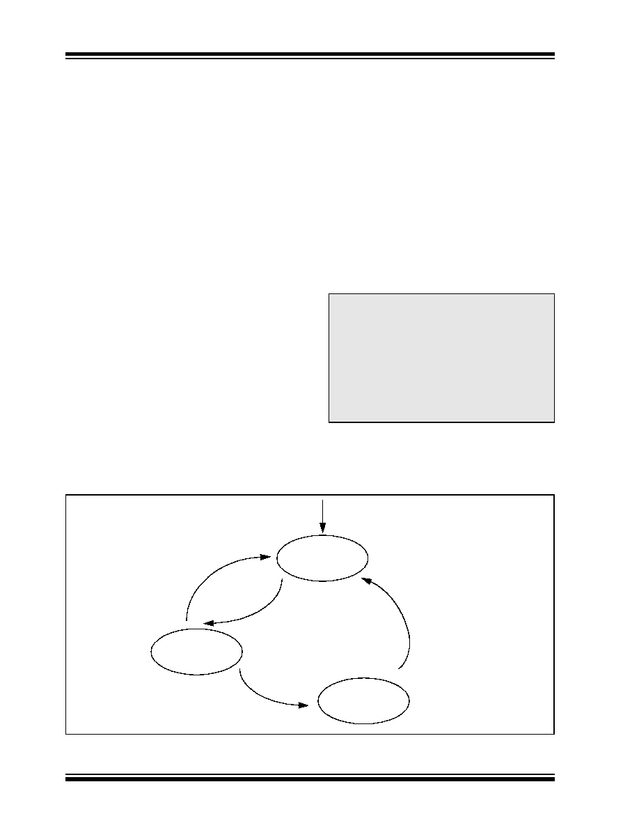
FIGURE 2-2:
ERROR MODES STATE DIAGRAM
Note:
The MCP2502X/5X, after going bus-off,
will
recover
back
to
error-active
automatically if the bus remains idle for
128 x 11 bits. OPTREG2.ERRE must be
set to force the MCP2502X/5X to enter
Listen-only mode instead of Normal mode
during bus recovery. The current error
mode
(except
for
bus-off)
of
the
MCP2502X/5X can be determined by
reading the EFLG register via the Read
CAN error message.
Bus-Off
Error-Active
Error-Passive
REC < 127 or
TEC < 127
REC > 127 or
TEC > 127
TEC > 255
RESET
128 occurrences of
11 consecutive
“recessive” bits
相关PDF资料 |
PDF描述 |
|---|---|
| MCP25020-I/SL | SPECIALTY MICROPROCESSOR CIRCUIT, PDSO14 |
| MCP25055-I/P | SPECIALTY MICROPROCESSOR CIRCUIT, PDIP14 |
| MCP25020-E/SL | SPECIALTY MICROPROCESSOR CIRCUIT, PDSO14 |
| MCP2510T-E/ST | 1 CHANNEL(S), 1M bps, LOCAL AREA NETWORK CONTROLLER, PDSO20 |
| MCP2510T-E/SOA03 | 1 CHANNEL(S), 1M bps, LOCAL AREA NETWORK CONTROLLER, PDSO18 |
相关代理商/技术参数 |
参数描述 |
|---|---|
| MCP25025-ISL | 制造商:MICROCHIP 制造商全称:Microchip Technology 功能描述:CAN I/O Expander Family |
| MCP25025T | 制造商:MICROCHIP 制造商全称:Microchip Technology 功能描述:CAN I/O Expander Family |
| MCP25025TE/P | 制造商:MICROCHIP 制造商全称:Microchip Technology 功能描述:CAN I/O Expander Family |
| MCP25025TE/SL | 制造商:MICROCHIP 制造商全称:Microchip Technology 功能描述:CAN I/O Expander Family |
| MCP25025TI/P | 制造商:MICROCHIP 制造商全称:Microchip Technology 功能描述:CAN I/O Expander Family |
发布紧急采购,3分钟左右您将得到回复。