- 您现在的位置:买卖IC网 > PDF目录20628 > MCP3905LT-E/SS (Microchip Technology)IC ENERGY METERING 24SSOP PDF资料下载
参数资料
| 型号: | MCP3905LT-E/SS |
| 厂商: | Microchip Technology |
| 文件页数: | 18/32页 |
| 文件大小: | 0K |
| 描述: | IC ENERGY METERING 24SSOP |
| 标准包装: | 2,100 |
| 输入阻抗: | 390 千欧 |
| 测量误差: | 0.1% |
| 电压 - 高输入/输出: | 2.4V |
| 电压 - 低输入/输出: | 0.85V |
| 电流 - 电源: | 2.7mA |
| 电源电压: | 4.5 V ~ 5.5 V |
| 测量仪表类型: | 单相 |
| 工作温度: | -40°C ~ 125°C |
| 安装类型: | 表面贴装 |
| 封装/外壳: | 24-SSOP(0.209",5.30mm 宽) |
| 供应商设备封装: | 24-SSOP |
| 包装: | 带卷 (TR) |
第1页第2页第3页第4页第5页第6页第7页第8页第9页第10页第11页第12页第13页第14页第15页第16页第17页当前第18页第19页第20页第21页第22页第23页第24页第25页第26页第27页第28页第29页第30页第31页第32页
�� �
�
�MCP3905A/05L/06A�
�The� multiplier� output� gives� the� product� of� the� two� high-�
�pass� filtered� channels,� corresponding� to� instantaneous�
�real� power.� Multiplying� two� sine� wave� signals� by� the�
�same� ω� frequency� gives� a� DC� component� and� a� 2� ω�
�component.� The� instantaneous� power� signal� contains�
�the� real� power� of� its� DC� component,� while� also� contain-�
�ing� 2� ω� components� coming� from� the� line� frequency�
�multiplication.� These� 2� ω� components� come� for� the� line�
�frequency� (and� its� harmonics)� and� must� be� removed� in�
�order� to� extract� the� real-power� information.� This� is�
�accomplished� using� the� low-pass� filter� and� DTF�
�converter.�
�4.6� Low-Pass� Filter� and� DTF�
�Converter�
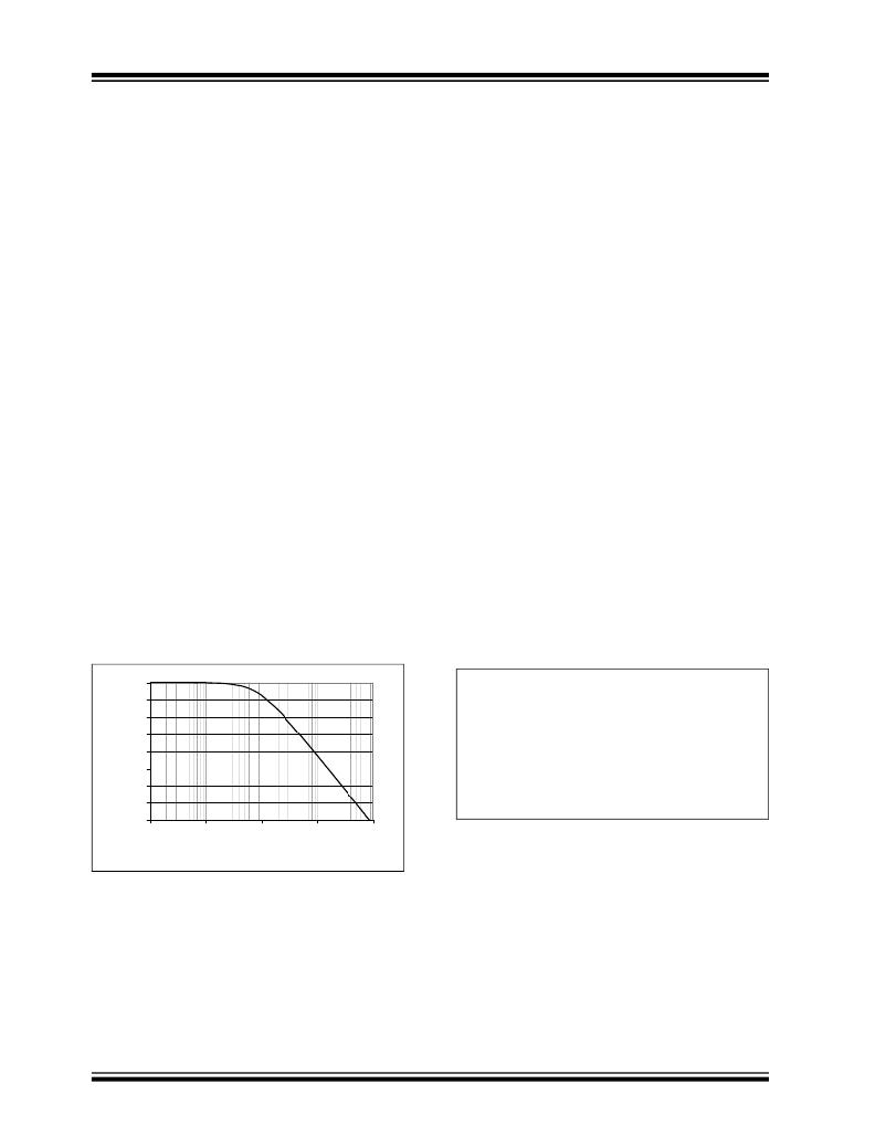
�The� MCP3905A/05L/06A� low-pass� filter� is� a� first-order�
�IIR� filter� that� extracts� the� active� real-power� information�
�(DC� component)� from� the� instantaneous� power� signal.�
�The� magnitude� response� of� this� filter� is� detailed� in�
�Figure� 4-5� .� Due� to� the� fact� that� the� instantaneous� power�
�The� equivalent� quantity� of� real� energy� required� to�
�output� a� pulse� is� much� larger� for� the� F� OUT0/1� outputs�
�than� the� HF� OUT� .� This� is� such� that� the� integration� period�
�for� the� F� OUT0/1� outputs� is� much� larger.� This� larger�
�integration� period� acts� as� another� low-pass� filter� so� that�
�the� output� ripple� due� to� the� 2� ω� components� is� minimal.�
�However,� these� components� are� not� totally� removed,�
�since� realized� low-pass� filters� are� never� ideal.� This� will�
�create� a� small� jitter� in� the� output� frequency.� Averaging�
�the� output� pulses� with� a� counter� or� a� MCU� in� the�
�application� will� then� remove� the� small� sinusoidal�
�content� of� the� output� frequency� and� filter� out� the�
�remaining� 2� ω� ripple.�
�HF� OUT� is� intended� to� be� used� for� calibration� purposes�
�due� to� its� instantaneous� power� content.� The� shorter�
�integration� period� of� HF� OUT� demands� that� the� 2� ω�
�component� be� given� more� attention.� Since� a� sinusoidal�
�signal� average� is� zero,� averaging� the� HF� OUT� signal� in�
�steady-state� conditions� will� give� the� proper� real� energy�
�value.�
�signal� has� harmonic� content� (coming� from� the� 2� ω�
�components� of� the� inputs),� and� since� the� filter� is� not�
�ideal,� there� will� be� some� ripple� at� the� output� of� the� low-�
�4.7�
�F� OUT0/1� and� HF� OUT� Output�
�Frequencies�
�pass� filter� at� the� harmonics� of� the� line� frequency.�
�The� cut-off� frequency� of� the� filter� (8.9� Hz)� has� been�
�chosen� to� have� sufficient� rejection� for� commonly-used�
�line� frequencies� (50� Hz� and� 60� Hz).� With� a� standard�
�input� clock� (MCLK� =� 3.58� MHz)� and� a� 50� Hz� line�
�frequency,� the� rejection� of� the� 2� ω� component� (100� Hz)�
�will� be� more� than� 20� dB.� This� equates� to� a� 2� ω�
�component� containing� 10� times� less� power� than� the�
�main� DC� component� (i.e.,� the� average� active� real�
�The� thresholds� for� the� accumulated� energy� are�
�different� for� F� OUT0/1� and� HF� OUT� (i.e.,� they� have�
�different� transfer� functions).� The� F� OUT0/1� allowed�
�output� frequencies� are� quite� low� in� order� to� allow�
�superior� integration� time� (see� Section� 4.6� “Low-Pass�
�Filter� and� DTF� Converter”� ).� The� F� OUT0/1� output�
�frequency� can� be� calculated� with� the� following�
�equation:�
�power).�
�EQUATION� 4-1:�
�F� OUT� FREQUENCY�
�OUTPUT� EQUATION�
�F� OUT� (� Hz� )� =� -----------------------------------------------------------�
�(� V� REF� )�
�0�
�-5�
�-10�
�Where:�
�8.06� � V� 0� � V� 1� � G� � F� C�
�2�
�-15�
�-20�
�-25�
�-30�
�-35�
�-40�
�V� 0� is� the� RMS� differential� voltage� on� Channel� 0�
�V� 1� is� the� RMS� differential� voltage� on� Channel� 1�
�G� is� the� PGA� gain� on� Channel� 0� (current� channel)�
�F� C� is� the� frequency� constant� selected�
�V� REF� is� the� voltage� reference�
�0.1�
�1�
�10�
�100�
�1000�
�For� a� given� DC� input� V,� the� DC� and� RMS� values� are�
�Frequency� (Hz)�
�equivalent.� For� a� given� AC� input� signal� with� peak-to-�
�FIGURE� 4-5:�
�LPF� Magnitude� Response�
�peak� amplitude� of� V,� the� equivalent� RMS� value� is�
�V/sqrt(2),� assuming� purely� sinusoidal� signals.� Note�
�(MCLK� =� 3.58� MHz).�
�The� output� of� the� low-pass� filter� is� accumulated� in� the�
�digital-to-frequency� converter.� This� accumulation� is�
�compared� to� a� different� digital� threshold� for� F� OUT0/1�
�and� HF� OUT� ,� representing� a� quantity� of� real� energy� mea-�
�sured� by� the� part.� Every� time� the� digital� threshold� on�
�F� OUT0/1� or� HF� OUT� is� crossed,� the� part� will� output� a�
�pulse� (See� Section� 4.7� “F� OUT0/1� and� HF� OUT� Output�
�Frequencies”� ).�
�DS22011B-page� 18�
�that� since� the� real� power� is� the� product� of� two� RMS�
�inputs,� the� output� frequencies� of� AC� signals� are� half� of�
�the� DC� inputs� ones,� again� assuming� purely� sinusoidal�
�AC� signals.� The� constant� F� C� depends� on� the� F� OUT0�
�and� F� OUT1� digital� settings.� Table� 4-3� shows� F� OUT0/1�
�output� frequencies� for� the� different� logic� settings.�
�?� 2006-2011� Microchip� Technology� Inc.�
�相关PDF资料 |
PDF描述 |
|---|---|
| MCP3905AT-E/SS | IC POWER METER 1-PHASE 24SSOP |
| GBM15DCBH | CONN EDGECARD 30POS R/A .156 SLD |
| ELT-5KT150LB | COIL 15UH 510MA STEP-UP SMD |
| MPG06K-E3/73 | DIODE 1A 800V MINI MPG06 |
| F951E225KRAAQ2 | CAP TANT 2.2UF 25V 10% SMD |
相关代理商/技术参数 |
参数描述 |
|---|---|
| MCP3905LT-I/SS | 功能描述:模数转换器 - ADC Dynamic Range Energy Meter IC RoHS:否 制造商:Texas Instruments 通道数量:2 结构:Sigma-Delta 转换速率:125 SPs to 8 KSPs 分辨率:24 bit 输入类型:Differential 信噪比:107 dB 接口类型:SPI 工作电源电压:1.7 V to 3.6 V, 2.7 V to 5.25 V 最大工作温度:+ 85 C 安装风格:SMD/SMT 封装 / 箱体:VQFN-32 |
| MCP3905RD-PM1 | 功能描述:电源管理IC开发工具 Energy Meter Ref Design RoHS:否 制造商:Maxim Integrated 产品:Evaluation Kits 类型:Battery Management 工具用于评估:MAX17710GB 输入电压: 输出电压:1.8 V |
| MCP3905T-I/SS | 功能描述:IC ENERGY METER 24-SSOP RoHS:是 类别:集成电路 (IC) >> PMIC - 能量测量 系列:- 产品培训模块:Lead (SnPb) Finish for COTS Obsolescence Mitigation Program 标准包装:2,500 系列:* |
| MCP3906 | 制造商:MICROCHIP 制造商全称:Microchip Technology 功能描述:Energy-Metering ICs with Active (Real) Power Pulse Output |
| MCP3906A | 制造商:MICROCHIP 制造商全称:Microchip Technology 功能描述:Energy Metering ICs with Active Real Power Pulse Output |
发布紧急采购,3分钟左右您将得到回复。