- 您现在的位置:买卖IC网 > PDF目录9316 > MCP4461T-103E/ML (Microchip Technology)IC DGTL POT 257TAPS 10K 20QFN PDF资料下载
参数资料
| 型号: | MCP4461T-103E/ML |
| 厂商: | Microchip Technology |
| 文件页数: | 67/100页 |
| 文件大小: | 0K |
| 描述: | IC DGTL POT 257TAPS 10K 20QFN |
| 标准包装: | 3,300 |
| 接片: | 257 |
| 电阻(欧姆): | 10k |
| 电路数: | 4 |
| 温度系数: | 标准值 150 ppm/°C |
| 存储器类型: | 非易失 |
| 接口: | I²C(设备位址) |
| 电源电压: | 2.7 V ~ 5.5 V |
| 工作温度: | -40°C ~ 125°C |
| 安装类型: | 表面贴装 |
| 封装/外壳: | 20-VFQFN 裸露焊盘 |
| 供应商设备封装: | 20-QFN 裸露焊盘(4x4) |
| 包装: | 带卷 (TR) |
第1页第2页第3页第4页第5页第6页第7页第8页第9页第10页第11页第12页第13页第14页第15页第16页第17页第18页第19页第20页第21页第22页第23页第24页第25页第26页第27页第28页第29页第30页第31页第32页第33页第34页第35页第36页第37页第38页第39页第40页第41页第42页第43页第44页第45页第46页第47页第48页第49页第50页第51页第52页第53页第54页第55页第56页第57页第58页第59页第60页第61页第62页第63页第64页第65页第66页当前第67页第68页第69页第70页第71页第72页第73页第74页第75页第76页第77页第78页第79页第80页第81页第82页第83页第84页第85页第86页第87页第88页第89页第90页第91页第92页第93页第94页第95页第96页第97页第98页第99页第100页
2010 Microchip Technology Inc.
DS22265A-page 69
MCP444X/446X
7.6
Increment Wiper
Normal and High Voltage
The Increment Command provides a quick and easy
method to modify the potentiometer’s wiper by +1 with
minimal overhead. The Increment Command will only
function on the volatile wiper setting memory locations
00h, 01h, 06h and 07h. The Increment Command to
Nonvolatile addresses will be ignored and will generate
a A.
When executing an Increment Command, the volatile
wiper setting will be altered from n to n+1 for each
Increment Command received. The value will
increment up to 100h max on 8-bit devices and 80h on
7-bit devices. If multiple Increment Commands are
received after the value has reached 100h (or 80h), the
value will not be incremented further. Table 7-4 shows
the Increment Command versus the current volatile
wiper value.
The Increment Command will most commonly be
performed on the Volatile Wiper locations until a
desired condition is met. The value in the Volatile Wiper
register would need to be read using a Read operation
in order to write the new setting to the corresponding
Nonvolatile wiper memory using a Write operation. The
MCP44XX is responsible for generating the A bits.
Refer to Figure 7-7 for the Increment Command
sequence. The sequence is terminated by the Stop
condition. So when executing a continuous command
string, the Increment command can be followed by any
other valid command. This means that writes do not
need to be to the same volatile memory address.
The advantage of using an Increment Command
instead of a read-modify-write series of commands is
speed and simplicity. The wiper will transition after each
Command Acknowledge when accessing the volatile
wiper registers.
TABLE 7-4:
INCREMENT OPERATION VS.
VOLATILE WIPER VALUE
7.6.1
THE HIGH VOLTAGE COMMAND
(HVC) SIGNAL
The High Voltage Command (HVC) signal is
multiplexed with Address 0 (A0) and is used to indicate
that the command, or sequence of commands, are in
the High Voltage mode. Signals > VIHH (~8.5V) on the
HVC/A0 pin puts MCP44XX devices into High Voltage
mode. High Voltage commands allow the device’s
WiperLock Technology and write protect features to be
enabled and disabled.
The HVC pin has an internal resistor connection to the
MCP44XX’s internal VDD signal.
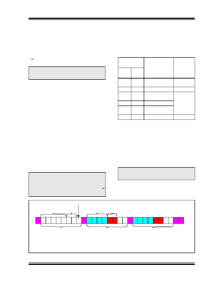
FIGURE 7-7:
I2C Increment Command Sequence.
Note:
Table 7-4 shows the valid addresses for
the Increment Wiper command. Other
addresses are invalid.
Note:
The command sequence can go from an
increment to any other valid command for
the
specified
address.
Issuing
an
increment or decrement to a nonvolatile
location will cause an error condition (A
will be generated).
Current Wiper
Setting
Wiper (W)
Properties
Increment
Command
Operates?
7-bit
Pot
8-bit
Pot
3FFh
081h
3FFh
101h
Reserved
(Full-Scale (W = A))
No
080h
100h
Full-Scale (W = A)
No
07Fh
041h
0FFh
081
W = N
040h
080h
W = N (Mid-Scale) Yes
03Fh
001h
07Fh
001
W = N
000h
Zero Scale (W = B) Yes
Note:
There is a required delay after the HVC pin
is driven to the VIHH level to the 1st edge
of the SCL pin.
Control Byte
INCR Command (n+1)
INCR Command (n+2)
1
010
S
1 A1 A0 0
0
AD AD AD AD
A1 x
X A
0
AD AD AD AD
1x
X A P (2)
0
1
2
3
43 21
Fixed
Address
Variable
Address
Device
Memory
Address
Command
Write bit
Note1:
Increment Command (INCR) only functions when accessing the volatile wiper
registers (AD3:AD0 = 00h, 01h, 06h, and 07h).
2:
This command sequence does not need to terminate (using the Stop bit) and can
change to any other desired command sequence (Increment, Read, or Write).
相关PDF资料 |
PDF描述 |
|---|---|
| VE-24Y-MW-F1 | CONVERTER MOD DC/DC 3.3V 66W |
| VE-B4X-IU-F1 | CONVERTER MOD DC/DC 5.2V 200W |
| VE-B4W-IU-F4 | CONVERTER MOD DC/DC 5.5V 200W |
| MS27473E18F35SD | CONN PLUG 66POS STRAIGHT W/SCKT |
| VE-B4W-IU-F2 | CONVERTER MOD DC/DC 5.5V 200W |
相关代理商/技术参数 |
参数描述 |
|---|---|
| MCP4461T-104E/ML | 功能描述:数字电位计 IC 100k I2C Qd Ch 8bit Nonvolatile memory RoHS:否 制造商:Maxim Integrated 电阻:200 Ohms 温度系数:35 PPM / C 容差:25 % POT 数量:Dual 每 POT 分接头:256 弧刷存储器:Volatile 缓冲刷: 数字接口:Serial (3-Wire, SPI) 描述/功能:Dual Volatile Low Voltage Linear Taper Digital Potentiometer 工作电源电压:1.7 V to 5.5 V 电源电流:27 uA 最大工作温度:+ 125 C 安装风格:SMD/SMT 封装 / 箱体:TQFN-16 封装:Reel |
| MCP4461T-104E/ST | 功能描述:数字电位计 IC 100k I2C Qd Ch 8bit Nonvolatile memory RoHS:否 制造商:Maxim Integrated 电阻:200 Ohms 温度系数:35 PPM / C 容差:25 % POT 数量:Dual 每 POT 分接头:256 弧刷存储器:Volatile 缓冲刷: 数字接口:Serial (3-Wire, SPI) 描述/功能:Dual Volatile Low Voltage Linear Taper Digital Potentiometer 工作电源电压:1.7 V to 5.5 V 电源电流:27 uA 最大工作温度:+ 125 C 安装风格:SMD/SMT 封装 / 箱体:TQFN-16 封装:Reel |
| MCP4461T-502E/ML | 功能描述:数字电位计 IC 5k I2C Qd Ch 8bit Nonvolatile memory RoHS:否 制造商:Maxim Integrated 电阻:200 Ohms 温度系数:35 PPM / C 容差:25 % POT 数量:Dual 每 POT 分接头:256 弧刷存储器:Volatile 缓冲刷: 数字接口:Serial (3-Wire, SPI) 描述/功能:Dual Volatile Low Voltage Linear Taper Digital Potentiometer 工作电源电压:1.7 V to 5.5 V 电源电流:27 uA 最大工作温度:+ 125 C 安装风格:SMD/SMT 封装 / 箱体:TQFN-16 封装:Reel |
| MCP4461T-502E/ST | 功能描述:数字电位计 IC 5k I2C Qd Ch 8bit Nonvolatile memory RoHS:否 制造商:Maxim Integrated 电阻:200 Ohms 温度系数:35 PPM / C 容差:25 % POT 数量:Dual 每 POT 分接头:256 弧刷存储器:Volatile 缓冲刷: 数字接口:Serial (3-Wire, SPI) 描述/功能:Dual Volatile Low Voltage Linear Taper Digital Potentiometer 工作电源电压:1.7 V to 5.5 V 电源电流:27 uA 最大工作温度:+ 125 C 安装风格:SMD/SMT 封装 / 箱体:TQFN-16 封装:Reel |
| MCP4461T-503E/ML | 功能描述:数字电位计 IC 50k I2C Qd Ch 8bit Nonvolatile memory RoHS:否 制造商:Maxim Integrated 电阻:200 Ohms 温度系数:35 PPM / C 容差:25 % POT 数量:Dual 每 POT 分接头:256 弧刷存储器:Volatile 缓冲刷: 数字接口:Serial (3-Wire, SPI) 描述/功能:Dual Volatile Low Voltage Linear Taper Digital Potentiometer 工作电源电压:1.7 V to 5.5 V 电源电流:27 uA 最大工作温度:+ 125 C 安装风格:SMD/SMT 封装 / 箱体:TQFN-16 封装:Reel |
发布紧急采购,3分钟左右您将得到回复。