- 您现在的位置:买卖IC网 > PDF目录9404 > MCP4662T-502E/MF (Microchip Technology)IC DGTL POT 5K 256TAPS 10-DFN PDF资料下载
参数资料
| 型号: | MCP4662T-502E/MF |
| 厂商: | Microchip Technology |
| 文件页数: | 51/92页 |
| 文件大小: | 0K |
| 描述: | IC DGTL POT 5K 256TAPS 10-DFN |
| 标准包装: | 1 |
| 接片: | 257 |
| 电阻(欧姆): | 5k |
| 电路数: | 2 |
| 温度系数: | 标准值 150 ppm/°C |
| 存储器类型: | 非易失 |
| 接口: | I²C(设备位址) |
| 电源电压: | 2.7 V ~ 5.5 V |
| 工作温度: | -40°C ~ 125°C |
| 安装类型: | 表面贴装 |
| 封装/外壳: | 10-VFDFN 裸露焊盘 |
| 供应商设备封装: | 10-DFN-EP(3x3) |
| 包装: | 标准包装 |
| 产品目录页面: | 677 (CN2011-ZH PDF) |
| 其它名称: | MCP4662T-502E/MFDKR |
第1页第2页第3页第4页第5页第6页第7页第8页第9页第10页第11页第12页第13页第14页第15页第16页第17页第18页第19页第20页第21页第22页第23页第24页第25页第26页第27页第28页第29页第30页第31页第32页第33页第34页第35页第36页第37页第38页第39页第40页第41页第42页第43页第44页第45页第46页第47页第48页第49页第50页当前第51页第52页第53页第54页第55页第56页第57页第58页第59页第60页第61页第62页第63页第64页第65页第66页第67页第68页第69页第70页第71页第72页第73页第74页第75页第76页第77页第78页第79页第80页第81页第82页第83页第84页第85页第86页第87页第88页第89页第90页第91页第92页
2008 Microchip Technology Inc.
DS22107A-page 55
MCP454X/456X/464X/466X
7.0
DEVICE COMMANDS
The MCP4XXX’s I2C command formats are specified in
this section. The I2C protocol does not specify how
commands are formatted.
The MCP4XXX supports four basic commands.
Depending on the location accessed determines the
commands that are supported.
For the Volatile Wiper Registers, these commands are:
Write Data
Read Data
Increment Data
Decrement Data
For the Non-Volatile wiper EEPROM, general purpose
data EEPROM, and the TCON Register these com-
mands are:
Write Data
Read Data
These commands have formats for both a single
command or continuous commands. These commands
are shown in Table 7-1.
Each command has two operational states. The
operational state determines if the device commands
control the special features (Write Protect and Wiper-
Lock Technology). These operational states are
referred to as:
Normal Serial Commands
High-Voltage Serial Commands
TABLE 7-1:
I2C COMMANDS
Normal serial commands are those where the HVC pin
is driven to VIH or VIL. With High-Voltage Serial Com-
mands, the HVC pin is driven to VIHH. In each mode,
there are four possible commands.
Additionally, there are two commands used to enable
or disable the special features (Write Protect and Wiper
Lock Technology) of the device. The commands are
special cases of the Increment and Decrement
High-Voltage Serial Command.
Table 7-2 shows the supported commands for each
memory location.
Table 7-3 shows an overview of all the device com-
mands and their interaction with other device features.
7.1
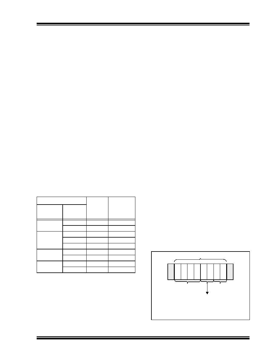
Command Byte
The MCP4XXX’s Command Byte has three fields: the
Address, the Command Operation, and 2 Data bits,
see Figure 7-1. Currently only one of the data bits is
defined (D8).
The device memory is accessed when the Master
sends a proper Command Byte to select the desired
operation. The memory location getting accessed is
contained in the Command Byte’s AD3:AD0 bits. The
action desired is contained in the Command Byte’s
C1:C0 bits, see Table 7-1. C1:C0 determines if the
desired
memory
location
will
be
read,
written,
Incremented (wiper setting +1) or Decremented (wiper
setting -1). The Increment and Decrement commands
are only valid on the volatile wiper registers, and in
High Voltage commands to enable/disable WiperLock
Technology and Software Write Protect.
If the Address bits and Command bits are not a valid
combination, then the MCP4XXX will generate a Not
Acknowledge pulse to indicate the invalid combination.
The I2C Master device must then force a Start Condi-
tion to reset the MCP4XXX’s 2C module.
D9 and D8 are the most significant bits for the digital
potentiometer’s wiper setting. The 8-bit devices utilize
D8 as their MSb while the 7-bit devices utilize D7 (from
the data byte) as it’s MSb.
FIGURE 7-1:
Command Byte Format.
Command
# of Bit
Clocks (1)
Operates on
Volatile/
Non-Volatile
memory
Operation
Mode
Write Data
Single
29
Both
Continuous
18n + 11
Volatile Only
Read Data
Single
29
Both
Random
48
Both
Continuous
18n + 11
Both (2)
Increment
(3)
Single
20
Volatile Only
Continuous
9n + 11
Volatile Only
Decrement
(3)
Single
20
Volatile Only
Continuous
9n + 11
Volatile Only
Note 1:
“n” indicates the number of times the
command operation is to be repeated.
2:
This command is useful to determine if a
non-volatile memory write cycle has
completed.
3:
High Voltage Increment and Decrement
commands on select non-volatile memory
locations enable/disable WiperLock
Technology and the software Write
Protect feature.
AA
D
3
A
D
2
A
D
1
A
D
0
C
1
C
0
D
9
D
8
A
MCP4XXX
COMMAND BYTE
00
= Write Data
01
= Increment
MSbits (Data)
10
= Decrement
11
= Read Data
Command Operation bits
Memory Address
相关PDF资料 |
PDF描述 |
|---|---|
| DS1501YZN+ | IC RTC WDOG Y2KC 5.0V 28-SOIC |
| DS1501WE+ | IC RTC WDOG Y2KC 3.3V 28-TSOP |
| DS1558Y+ | IC RTC W/NV RAM 5V 48-TQFP |
| MCP4662T-104E/MF | IC DGTL POT 100K 256TAPS 10-DFN |
| DS1558W+ | IC RTC W/NV RAM 3.3V 48-LQFP |
相关代理商/技术参数 |
参数描述 |
|---|---|
| MCP4662T-503E/MF | 功能描述:数字电位计 IC Sngl 8B NV I2C Rheo RoHS:否 制造商:Maxim Integrated 电阻:200 Ohms 温度系数:35 PPM / C 容差:25 % POT 数量:Dual 每 POT 分接头:256 弧刷存储器:Volatile 缓冲刷: 数字接口:Serial (3-Wire, SPI) 描述/功能:Dual Volatile Low Voltage Linear Taper Digital Potentiometer 工作电源电压:1.7 V to 5.5 V 电源电流:27 uA 最大工作温度:+ 125 C 安装风格:SMD/SMT 封装 / 箱体:TQFN-16 封装:Reel |
| MCP4662T-503E/UN | 功能描述:数字电位计 IC Sngl 8B NV I2C Rheo RoHS:否 制造商:Maxim Integrated 电阻:200 Ohms 温度系数:35 PPM / C 容差:25 % POT 数量:Dual 每 POT 分接头:256 弧刷存储器:Volatile 缓冲刷: 数字接口:Serial (3-Wire, SPI) 描述/功能:Dual Volatile Low Voltage Linear Taper Digital Potentiometer 工作电源电压:1.7 V to 5.5 V 电源电流:27 uA 最大工作温度:+ 125 C 安装风格:SMD/SMT 封装 / 箱体:TQFN-16 封装:Reel |
| MCP46XXDM-PTPLS | 功能描述:数字电位计 IC MCP46XX PICtail Plus Daughter Board RoHS:否 制造商:Maxim Integrated 电阻:200 Ohms 温度系数:35 PPM / C 容差:25 % POT 数量:Dual 每 POT 分接头:256 弧刷存储器:Volatile 缓冲刷: 数字接口:Serial (3-Wire, SPI) 描述/功能:Dual Volatile Low Voltage Linear Taper Digital Potentiometer 工作电源电压:1.7 V to 5.5 V 电源电流:27 uA 最大工作温度:+ 125 C 安装风格:SMD/SMT 封装 / 箱体:TQFN-16 封装:Reel |
| MCP46XXEV | 功能描述:数字电位计开发工具 MCP46XX Eval Board RoHS:否 制造商:Arduino 产品:TinkerKit Rotary Potentiometers 工具用于评估:TinkerKit 电阻:4.7 kOhms 工作电源电压:0 V to 5 V |
| MCP4706A0T-015E/CH | 制造商:Microchip Technology Inc 功能描述:IC, DAC, 16 bit, 3.4 MSPS, SOT-23-6; Resolution (Bits):8bit; Input Channel Type:Single Ended; Supply Voltage Range:2.7V to 5.5V; Digital IC Case Style:SOT-23; No. of Pins:6; Data Interface:I2C, Serial; Supply Current:210A |
发布紧急采购,3分钟左右您将得到回复。