- 您现在的位置:买卖IC网 > PDF目录19703 > MCZ34653EF (Freescale Semiconductor)IC HOTSWAP CTRLR 1A NEG 8-SOIC PDF资料下载
参数资料
| 型号: | MCZ34653EF |
| 厂商: | Freescale Semiconductor |
| 文件页数: | 10/24页 |
| 文件大小: | 1649K |
| 描述: | IC HOTSWAP CTRLR 1A NEG 8-SOIC |
| 标准包装: | 98 |
| 类型: | 热交换开关 |
| 应用: | 通用 |
| 内部开关: | 是 |
| 电流限制: | 1A |
| 电源电压: | 36 V ~ 80 V |
| 工作温度: | -40°C ~ 85°C |
| 安装类型: | 表面贴装 |
| 封装/外壳: | 8-SOIC(0.154",3.90mm 宽) |
| 供应商设备封装: | 8-SOICN |
| 包装: | 管件 |
Analog Integrated Circuit Device Data
10
Freescale Semiconductor
34653
FUNCTIONAL DEVICE OPERATION
OPERATIONAL MODES
rchived by Freescale Semiconductor, Inc., 2008
FUNCTIONAL DEVICE OPERATION
OPERATIONAL MODES
START-UP SEQUENCE
When power is first applied to the 34653 by connecting the
VIN pin to the negative voltage rail and the VPWR pin to the
positive voltage rail, the 34653 keeps the Power MOSFET
turned off, deactivates the power good output signals, and
resets the retry counter. If the device is disabled, no further
activities will occur and power-up would not start. If the device
is enabled, it starts to establish an internally regulated supply
voltage required for the internal circuitry. The Power
MOSFET will stay off until the start of the charging process.
After the Power-ON Reset (POR) and once the
Undervoltage Lockout (UVLO) threshold is cleared, the
34653 checks for external components on two pins ILIM
and ICHG to set the levels of the Overcurrent Limit and the
Charging Current Limit, respectively. The device then
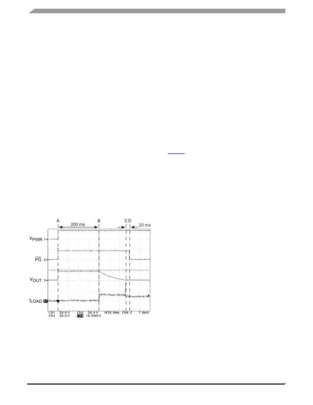
initiates the start-up timer (Point A in Figure 6
) and checks for
the start-up conditions (see next paragraph). The duration of
the timer is a default value. For undervoltage and overvoltage
faults during power up the 34652 retries infinitely until normal
input voltage is attained. If the die temperature ever
increased beyond the thermal shutdown threshold or the
device is disabled, then the start-up timer resets and the retry
counter increments. If after 10 retries the die temperature is
still high and the device is still disabled, the 34652 will not
retry again and the power in the device must be recycled or
the device must be disabled to reset the retry counter.
Figure 6. Start-Up Sequence
Start-Up Conditions
The start-up conditions are as follows:
" Input voltage is below the overvoltage turn-off threshold.
This threshold is a default.
" Input voltage is above the undervoltage turn-off threshold.
This threshold is a default.
" Die temperature is less than the thermal shutdown
temperature.
" Device is enabled.
If the start-up conditions are satisfied for a time equal to
the length of the start-up timer and the retry counter is less
than or equal to 10, the device starts to turn on the Power
MOSFET gradually to control the inrush current that charges
up the load capacitor to eventually switch on the load (Point B
in Figure 6
).
Charging Process
When charging a capacitor from a fixed voltage source, a
definite amount of energy will be dissipated in the control
circuit, no matter what the control algorithm is. This energy is
equal to the energy transferred to the capacitor ?CV
2
.
With this in mind, the Power MOSFET in the 34653 cannot
absorb this pulse of energy instantaneously, so the pulse
must be dissipated over time. To limit the peak power
dissipation in the Power MOSFET and to spread out the
duration of the energy dissipation in the Power MOSFET, the
circuit uses a two-level current approach to controlling the
inrush current and switching on the load as explained in the
following paragraphs.
When the Power MOSFET is turned on, the current limit is
set gradually from 0 A to I
CHG
(between Points A and B in
Figure 7
). The low charging current value and the gradual
rise time of I
CHG
are either defaults or they can be user
programmable (2.0 ms rise time in the example in Figure 7
).
The low charging current value of I
CHG
is intended to limit the
temperature increase during the load capacitor charging
process, and the gradual rise to I
CHG
is to prevent transient
dips in the input voltage due to sharp increases in the current.
This prevents the input voltage from drooping due to current
steps acting on the input line inductance, and that in turn
prevents a premature activation of the UV detection circuit.
相关PDF资料 |
PDF描述 |
|---|---|
| CR-2450/H1AN | BATT LITH COIN 3V CELL PC PINS |
| GQM2195C2E8R2CB12D | CAP CER 8.2PF 250V NP0 0805 |
| 183-009-213R171 | CONN DB9 FEMALE .590" R/A NICKEL |
| MCZ34652EF | IC HOTSWAP CTRLR 2A NEG 16SOIC |
| ASC35DRTS | CONN EDGECARD 70POS .100 DIP SLD |
相关代理商/技术参数 |
参数描述 |
|---|---|
| MCZ34653EF/R2 | 制造商:FREESCALE 制造商全称:Freescale Semiconductor, Inc 功能描述:1.0 A Negative Voltage Hot Swap Controller |
| MCZ34653EFR2 | 功能描述:热插拔功率分布 Hot Swap Controller 1.0 Neg Vltg RoHS:否 制造商:Texas Instruments 产品:Controllers & Switches 电流限制: 电源电压-最大:7 V 电源电压-最小:- 0.3 V 工作温度范围: 功率耗散: 安装风格:SMD/SMT 封装 / 箱体:MSOP-8 封装:Tube |
| MCZ34670EG | 功能描述:热插拔功率分布 POWER OVER ETHERNET RoHS:否 制造商:Texas Instruments 产品:Controllers & Switches 电流限制: 电源电压-最大:7 V 电源电压-最小:- 0.3 V 工作温度范围: 功率耗散: 安装风格:SMD/SMT 封装 / 箱体:MSOP-8 封装:Tube |
| MCZ34670EG/R2 | 制造商:FREESCALE 制造商全称:Freescale Semiconductor, Inc 功能描述:IEEE 802.3af PD With Current Mode Switching Regulator |
| MCZ34670EGR2 | 功能描述:热插拔功率分布 POWER OVER ETHERNET RoHS:否 制造商:Texas Instruments 产品:Controllers & Switches 电流限制: 电源电压-最大:7 V 电源电压-最小:- 0.3 V 工作温度范围: 功率耗散: 安装风格:SMD/SMT 封装 / 箱体:MSOP-8 封装:Tube |
发布紧急采购,3分钟左右您将得到回复。