参数资料
| 型号: | MIC2150YML TR |
| 厂商: | Micrel Inc |
| 文件页数: | 18/27页 |
| 文件大小: | 0K |
| 描述: | IC REG CTRLR BUCK PWM 24MLF |
| 标准包装: | 1 |
| PWM 型: | 电流/电压模式 |
| 输出数: | 2 |
| 频率 - 最大: | 550kHz |
| 占空比: | 80% |
| 电源电压: | 4.5 V ~ 14.5 V |
| 降压: | 是 |
| 升压: | 无 |
| 回扫: | 无 |
| 反相: | 无 |
| 倍增器: | 无 |
| 除法器: | 无 |
| Cuk: | 无 |
| 隔离: | 无 |
| 工作温度: | -40°C ~ 125°C |
| 封装/外壳: | 24-VFQFN 裸露焊盘,24-MLF? |
| 包装: | 标准包装 |
| 其它名称: | 576-3746-6 |
第1页第2页第3页第4页第5页第6页第7页第8页第9页第10页第11页第12页第13页第14页第15页第16页第17页当前第18页第19页第20页第21页第22页第23页第24页第25页第26页第27页
�� �
�
�Micrel,� Inc.�
�operating� conditions.� The� detailed� analysis� for� achieving�
�this� is� covered� in� other� texts� and� will� not� be� covered�
�here.� The� following� is� a� method� for� calculating� the�
�correct� values� for� stability.�
�Ceramic� Output� Capacitor� Designs�
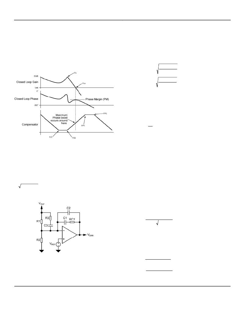
�The� closed� loop� Bode� plot� response� for� a� correctly�
�compensated� ceramic� output� capacitor� design� is� shown�
�MIC2150�
�margin� (typically� 50� degrees� will� ensure� system� stability�
�over� all� conditions).�
�Fco� <� Fs/5�
�PM� =� 50� degrees�
�Place� the� two� phase� boost� break� frequencies� such� that�
�our� maximum� phase� boost� occurs� at� the� desired�
�crossover� frequency� Fco.�
�below.�
�FZ� 2� =� Fco� �
�FP� 1� =� Fco� �
�1� ?� Sin(PM)�
�1� +� Sin� (� PM� )�
�1� +� Sin(PM)�
�1� ?� Sin� (� PM� )�
�FZ1� must� be� somewhere� below� or� equal� to� FZ2.� Placing�
�it� at� one� half� FZ2� helps� to� spread� the� frequency� range� of�
�the� phase� boost.�
�FZ� 1� =� FZ� 2� /� 2�
�Finally,� place� the� noise� suppression� pole� at� one� half� the�
�switching� frequency.�
�FP� 2� =�
�F� S�
�2�
�The� calculation� of� the� required� components� to� achieve�
�FP1,� FP2,� FZ1� and� FZ2� for� this� circuit� is� ideal� for� a�
�Figure� 11.� Ceramic� Output� Capacitor� Bode� Plot�
�The� power� inductor� and� output� capacitor� create� the�
�resonant� frequency� at� Fo.� It� is� preferred� to� make� the�
�desired� crossover� frequency� (loop� bandwidth)� greater�
�than� this� at� Fco� with� a� phase� margin� (PM)� of� typically� 50�
�degrees.� The� maximum� phase� boost,� on� a� log� scale,�
�occurs� approximately� half� way� between� the� highest� zero�
�(FZ2)� and� the� lowest� pole� (FP1).� To� be� precise,� it� is�
�at� FZ� 2� � FP� 1� .� The� required� compensation� network� for�
�this� is� a� double� pole,� double� zero� or� type� III� network�
�shown� in� Figure� 12.�
�spreadsheet� which� is� available� on� the� Micrel� website.�
�However,� they� can� also� be� calculated� using� the� following�
�method:�
�Collect� All� Known� Circuit� Parameters�
�L:� Inductor� value�
�C� OUT� :� Output� capacitor� value�
�ESR:� Output� capacitor� ESR.�
�Fco:� Desired� crossover� frequency�
�V� RAMP� :� Internal� ramp� voltage� =� 1.5V�
�V� REF� :� Internal� reference� voltage� =� 0.7V�
�V� IN� :� Maximum� input� voltage� of� the� converter�
�Calculating� Network� Values�
�Fo� =�
�1�
�2� ×� π� ×� L� ×� C� OUT�
�Choose� RC1� value:�
�This� can� be� any� reasonable� value� up� to� 10k� Ω� ,� but� in�
�order� to� keep� the� values� of� R1� and� C2� within� practical�
�limits,� this� ‘factor’� can� be� useful.�
�Rc1� =� 25k/Fo�
�Figure� 12.� Type� III� Compensation� Network�
�Placement� of� the� 2� Poles� and� 2� Zeros�
�Choose� a� loop� bandwidth/crossover� frequency� (Fco)� at�
�less� than� one� fifth� switching� frequency� and� a� phase�
�August� 2009�
�18�
�C� 1� =�
�C� 2� =�
�1�
�2� ×� π� ×� RC� 1� ×� FZ� 1�
�1�
�2� ×� π� ×� RC� 1� ×� FP� 2�
�M9999-082809-A�
�(408)� 944-0800�
�相关PDF资料 |
PDF描述 |
|---|---|
| MIC2156YML TR | IC REG CTRLR BUCK PWM VM 32MLF |
| MIC2159YMME | IC REG CTRLR BUCK PWM VM 10-MSOP |
| MIC2164YMM | IC REG CTRLR BUCK PWM 10-MSOP |
| MIC2165YMME TR | IC REG CTRLR BUCK PWM 10TSOP |
| MIC2166YMME TR | IC REG CTRLR PWM HYBRID 10TSOP |
相关代理商/技术参数 |
参数描述 |
|---|---|
| MIC2151 | 制造商:MICREL 制造商全称:Micrel Semiconductor 功能描述:2-Phase Dual Output PWM Synchronous Buck Control IC |
| MIC2151YML | 制造商:Micrel 功能描述:Micrel MIC2151YML |
| MIC2155 | 制造商:MICREL 制造商全称:Micrel Semiconductor 功能描述:2-Phase, Single Output, PWM Synchronous Buck Control IC |
| MIC2155_0911 | 制造商:MICREL 制造商全称:Micrel Semiconductor 功能描述:Two-Phase, Single-Output, PWM Synchronous Buck Control IC |
| MIC2155YML | 制造商:Micrel 功能描述:The Micrel MIC2155YML is a 50A Synchronous Buck Regulator. |
发布紧急采购,3分钟左右您将得到回复。