- 您现在的位置:买卖IC网 > PDF目录14536 > MIC23250-3BYMT TR (Micrel Inc)IC REG BUCK SYNC 0.4A DL 10TMLF PDF资料下载
参数资料
| 型号: | MIC23250-3BYMT TR |
| 厂商: | Micrel Inc |
| 文件页数: | 12/20页 |
| 文件大小: | 0K |
| 描述: | IC REG BUCK SYNC 0.4A DL 10TMLF |
| 产品培训模块: | MIC23xxx HyperLight Load™ Regulators |
| 标准包装: | 1 |
| 系列: | HyperLight Load® |
| 类型: | 降压(降压) |
| 输出类型: | 固定 |
| 输出数: | 2 |
| 输出电压: | 0.9V,1.1V |
| 输入电压: | 2.7 V ~ 5.5 V |
| PWM 型: | 混合物 |
| 频率 - 开关: | 4MHz |
| 电流 - 输出: | 400mA |
| 同步整流器: | 是 |
| 工作温度: | -40°C ~ 125°C |
| 安装类型: | 表面贴装 |
| 封装/外壳: | 10-UFDFN,10-TMLF? |
| 包装: | 标准包装 |
| 供应商设备封装: | 10-TMLF?(2x2) |
| 产品目录页面: | 1094 (CN2011-ZH PDF) |
| 其它名称: | 576-3255-6 |
�� �
�
�I� PEAK� =� ?� I� OUT� +� V� OUT� ??� ??� ?�
�?� ?�
�?�
�Micrel,� Inc.�
�Applications� Information�
�The� MIC23250� is� designed� for� high� performance� with� a�
�small� solution� size.� With� a� dual� 400mA� output� inside� a� tiny�
�2mm� x� 2mm� Thin� MLF� ?� package� and� requiring� only� six�
�external� components,� the� MIC23250� meets� today’s�
�miniature� portable� electronic� device� needs.� While� small�
�solution� size� is� one� of� its� advantages,� the� MIC23250� is� big�
�in� performance.� Using� the� HyperLight� Load?� switching�
�scheme,� the� MIC23250� is� able� to� maintain� high� efficiency�
�throughout� the� entire� load� range� while� providing� ultra-fast�
�load� transient� response.� Even� with� all� the� given� benefits,�
�the� MIC23250� can� be� as� easy� to� use� as� linear� regulators.�
�The� following� sections� provide� an� over� view� of�
�implementing� MIC23250� into� related� applications�
�Input� Capacitor�
�A� minimum� of� 2.2μF� ceramic� capacitor� should� be� placed�
�close� to� the� VIN� pin� and� PGND� pin� for� bypassing.� A� TDK�
�C1608X5R0J475K,� size� 0603,� 4.7μF� ceramic� capacitor� is�
�recommended� based� upon� performance,� size� and� cost.� A�
�X5R� or� X7R� temperature� rating� is� recommended� for� the�
�input� capacitor.� Y5V� temperature� rating� capacitors,� aside�
�from� losing� most� of� their� capacitance� over� temperature,�
�can� also� become� resistive� at� high� frequencies.� This�
�reduces� their� ability� to� filter� out� high� frequency� noise.�
�Output� Capacitor�
�The� MIC23250� was� designed� for� use� with� a� 2.2μF� or�
�greater� ceramic� output� capacitor.� Increasing� the� output�
�capacitance� will� lower� output� ripple� and� improve� load�
�transient� response� but� could� increase� solution� size� or� cost.�
�A� low� equivalent� series� resistance� (ESR)� ceramic� output�
�capacitor� such� as� the� TDK� C1608X5R0J475K,� size� 0603,�
�4.7μF� ceramic� capacitor� is� recommended� based� upon�
�performance,� size� and� cost.� Either� the� X7R� or� X5R�
�temperature� rating� capacitors� are� recommended.� The� Y5V�
�and� Z5U� temperature� rating� capacitors,� aside� from� the�
�undesirable� effect� of� their� wide� variation� in� capacitance�
�over� temperature,� become� resistive� at� high� frequencies.�
�Inductor� Selection�
�Inductor� selection� will� be� determined� by� the� following� (not�
�necessarily� in� the� order� of� importance);�
�MIC23250�
�Maximum� current� ratings� of� the� inductor� are� generally�
�given� in� two� methods;� permissible� DC� current� and�
�saturation� current.� Permissible� DC� current� can� be� rated�
�either� for� a� 40°C� temperature� rise� or� a� 10%� to� 20%� loss� in�
�inductance.� Ensure� the� inductor� selected� can� handle� the�
�maximum� operating� current.� When� saturation� current� is�
�specified,� make� sure� that� there� is� enough� margin� so� that�
�the� peak� current� of� the� inductor� does� not� cause� it� to�
�saturate.� Peak� current� can� be� calculated� as� follows:�
�?� ?� 1� ?� V� OUT� /� V� IN� ?� ?�
�?� 2� � f� � L�
�As� shown� by� the� previous� calculation,� the� peak� inductor�
�current� is� inversely� proportional� to� the� switching� frequency�
�and� the� inductance;� the� lower� the� switching� frequency� or�
�the� inductance� the� higher� the� peak� current.� As� input�
�voltage� increases� the� peak� current� also� increases.�
�The� size� of� the� inductor� depends� on� the� requirements� of�
�the� application.� Refer� to� the� Application� Circuit� and� Bill� of�
�Material� for� details.�
�DC� resistance� (DCR)� is� also� important.� While� DCR� is�
�inversely� proportional� to� size,� DCR� can� represent� a�
�significant� efficiency� loss.� Refer� to� the� Efficiency�
�Considerations.�
�Compensation�
�The� MIC23250� is� designed� to� be� stable� with� a� 0.47μH� to�
�4.7μH� inductor� with� a� minimum� of� 2.2μF� ceramic� (X5R)�
�output� capacitor.� For� the� adjustable� MIC23250,� the� total�
�feedback� resistance� should� be� kept� around� 1M� ?� to� reduce�
�current� loss� down� the� feedback� resistor� network.� This�
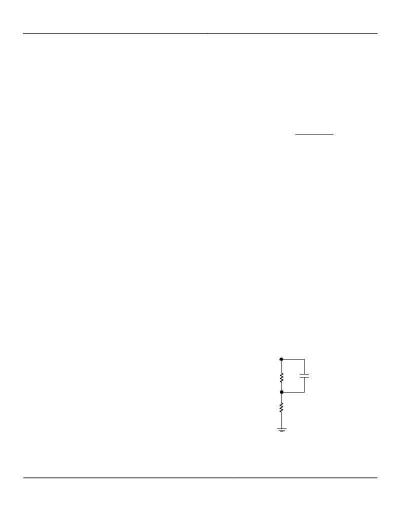
�helps� to� improve� efficiency.� A� feed-forward� capacitor�
�(CFF)� of� 120pF� must� be� used� in� conjunction� with� the�
�external� feedback� resistors� to� reduce� the� effects� of�
�parasitic� capacitance� that� is� inherent� of� most� circuit� board�
�layouts.� Figure� 1� and� Table� 1� shows� the� recommended�
�feedback� resistor� values� along� with� the� recommended�
�feed-forward� capacitor� values� for� the� MIC23250� adjustable�
�device.�
�?�
�?�
�?�
�?�
�Inductance�
�Rated� current� value�
�Size� requirements�
�DC� resistance� (DCR)�
�R� TOP�
�R� BOTTOM�
�C� FF�
�The� MIC23250� was� designed� for� use� with� an� inductance�
�range� from� 0.47μH� to� 4.7μH.� Typically,� a� 1μH� inductor� is�
�recommended� for� a� balance� of� transient� response,�
�efficiency� and� output� ripple.� For� faster� transient� response� a�
�0.47μH� inductor� may� be� used.� For� lower� output� ripple,� a�
�4.7μH� is� recommended.�
�Figure� 1.� Feedback� Resistor� Network�
�June� 2010�
�12�
�M9999-061110-E�
�相关PDF资料 |
PDF描述 |
|---|---|
| V72B3V3T100B3 | CONVERTER MOD DC/DC 3.3V 100W |
| V48C8T150BL2 | CONVERTER MOD DC/DC 8V 150W |
| V48C8T150BF3 | CONVERTER MOD DC/DC 8V 150W |
| V48C8T150B3 | CONVERTER MOD DC/DC 8V 150W |
| IHSM7832ER100K | INDUCTOR POWER 10UH 5.0A SMD |
相关代理商/技术参数 |
参数描述 |
|---|---|
| MIC23250-AAYMT | 制造商:Micrel Inc 功能描述:Dual 400mA Buck Reg w HyperLight Load |
| MIC23250-AAYMT EV | 功能描述:电源管理IC开发工具 High Efficiency Dual 400mA Synchronous Buck Switcher - Evaluation Board RoHS:否 制造商:Maxim Integrated 产品:Evaluation Kits 类型:Battery Management 工具用于评估:MAX17710GB 输入电压: 输出电压:1.8 V |
| MIC23250-AAYMT TR | 功能描述:直流/直流开关调节器 High Efficiency Dual 400mA Synchronous Buck Switcher RoHS:否 制造商:International Rectifier 最大输入电压:21 V 开关频率:1.5 MHz 输出电压:0.5 V to 0.86 V 输出电流:4 A 输出端数量: 最大工作温度: 安装风格:SMD/SMT 封装 / 箱体:PQFN 4 x 5 |
| MIC23250-AAYMTEV | 制造商:Micrel Inc 功能描述:Evaluation Board MIC23250-AAYMT |
| MIC23250-AAYMT-EV | 功能描述:MIC23250 HyperLight Load? DC/DC, Step Down 2, Non-Isolated Outputs Evaluation Board 制造商:microchip technology 系列:HyperLight Load? 零件状态:有效 主要用途:DC/DC,步降 输出和类型:2,非隔离 功率 - 输出:- 电压 - 输出:1.8V,1.8V 电流 - 输出:400mA,400mA 电压 - 输入:2.7 V ~ 5.5 V 稳压器拓扑:降压 频率 - 开关:4MHz 板类型:完全填充 所含物品:板 使用的 IC/零件:MIC23250 标准包装:1 |
发布紧急采购,3分钟左右您将得到回复。