- 您现在的位置:买卖IC网 > Datasheet目录343 > MIC4100YM (Micrel Inc)IC DRIVER MOSFET 100V CMOS 8SOIC Datasheet资料下载
参数资料
| 型号: | MIC4100YM |
| 厂商: | Micrel Inc |
| 文件页数: | 15/18页 |
| 文件大小: | 0K |
| 描述: | IC DRIVER MOSFET 100V CMOS 8SOIC |
| 标准包装: | 95 |
| 配置: | 半桥 |
| 输入类型: | 非反相 |
| 延迟时间: | 27ns |
| 电流 - 峰: | 2A |
| 配置数: | 1 |
| 输出数: | 2 |
| 高端电压 - 最大(自引导启动): | 118V |
| 电源电压: | 9 V ~ 16 V |
| 工作温度: | -40°C ~ 125°C |
| 安装类型: | 表面贴装 |
| 封装/外壳: | 8-SOIC(0.154",3.90mm 宽) |
| 供应商设备封装: | 8-SOIC |
| 包装: | 管件 |
| 产品目录页面: | 1109 (CN2011-ZH PDF) |
| 其它名称: | 576-1183 |
�� �
�
�Micrel,� Inc.�
�capacitors� are� recommended� for� most� applications.� The�
�minimum� capacitance� value� should� be� increased� if� low�
�voltage� capacitors� are� use� since� even� good� quality�
�dielectric� capacitors,� such� as� X5R,� will� lose� 40%� to� 70%� of�
�MIC4100/1�
�is� from� the� source� of� the� MOSFET� and� back� to� capacitor�
�C� B� .� The� high-side� circuit� return� path� usually� does� not� have�
�a� low� impedance� ground� plane� so� the� etch� connections� in�
�this� critical� path� should� be� short� and� wide� to� minimize�
�their� capacitance� value� at� the� rated� voltage.�
�parasitic� inductance.� As�
�with�
�the� low-side�
�circuit,�
�Placement� of� the� decoupling� capacitors� is� critical.� The�
�bypass� capacitor� for� Vdd� should� be� placed� as� close� as�
�possible� between� the� Vdd� and� Vss� pins.� The� bypass�
�capacitor� (C� B� )� for� the� HB� supply� pin� must� be� located� as�
�close� as� possible� between� the� HB� and� HS� pins.� The� etch�
�connections� must� be� short,� wide� and� direct.� The� use� of� a�
�ground� plane� to� minimize� connection� impedance� is�
�recommended.� Refer� to� the� section� on� layout� and�
�component� placement� for� more� information.�
�The� voltage� on� the� bootstrap� capacitor� drops� each� time� it�
�delivers� charge� to� turn� on� the� MOSFET.� The� voltage� drop�
�depends� on� the� gate� charge� required� by� t� he� MOSFET.�
�impedance� between� the� MOSFET� source� and� the�
�decoupling� capacitor� causes� negative� voltage� feedback�
�which� fights� the� turn-on� of� the� MOSFET.�
�It� is� important� to� note� that� capacitor� CB� must� be� placed�
�close� to� the� HB� and� HS� pins.� This� capacitor� not� only�
�provides� all� the� energy� for� turn-on� but� it� m� ust� also� keep� HB�
�pin� noise� and� ripple� low� for� proper� operation� of� the� high-�
�side� drive� circuitry.�
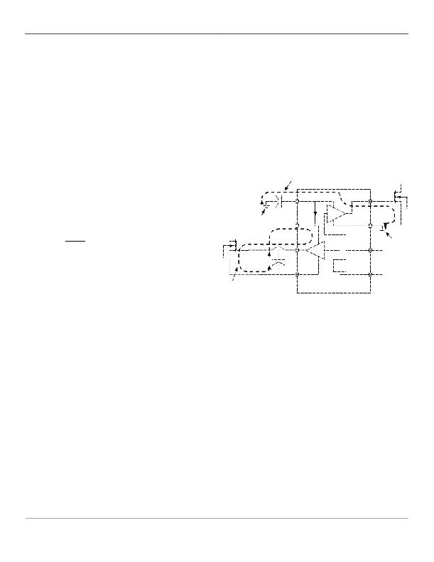
�Low-side� drive� turn-on�
�current� path�
�Most� MOSFET� specifications� specify� gate� charge� vs.� Vgs�
�voltage.� Based� on� this� information� and� a� recommended�
�Vdd�
�LO�
�?� V� HB� of� less� than� 0.1V,� the� minimum� value� of� bootstrap�
�capacitance� is� calculated� as:�
�gnd�
�plane�
�C� Vdd�
�HB�
�Vss�
�C� B� ≥�
�Q� gate�
�?� V� HB�
�HO�
�LI�
�gnd�
�plane�
�where� :� Q� gate� =� Total� Gate� Charge� at� V� HB�
�?� V� HB� =� Voltage� drop� at� the� HB� pin�
�C� B�
�HS�
�Level�
�shift�
�HI�
�The� decoupling� capacitor� for� the� Vdd� input� may� be�
�calculated� in� with� the� same� formula;� however,� the� two�
�capacitors� are� usually� equal� in� value.�
�High-side� drive� turn-on�
�current� path�
�Turn-On� Current� Paths�
�Figure� 9�
�Grounding,� Component� Placement� and� Circuit� Layout�
�Nanosecond� switching� speeds� and� am� pere� peak� currents�
�in� and� around� the� MIC4100� and� MIC4101� drivers� require�
�proper� placement� and� trace� routing� of� all� components.�
�Improper� placement� may� cause� degraded� noise� immunity,�
�false� switching,� excessive� ringing� or� circuit� latch-up.�
�Figure� 9� shows� the� critical� current� paths� when� the� driver�
�outputs� go� high� and� turn� on� the� external� MOSFETs.� It� also�
�helps� demonstrate� the� need� for� a� low� impedance� g� round�
�plane.� Charge� needed� to� turn-on� the� MOSFET� gates�
�comes� from� the� decoupling� capacitors� C� VDD� and� C� B� .�
�Current� in� the� low-side� gate� driver� flows� from� C� VDD� through�
�the� internal� driver,� into� the� MOSFET� gate� and� out� the�
�Source.� The� return� connection� back� to� the� decoupling�
�capacitor� is� made� through� the� ground� plane.� Any�
�inductance� or� resistance� in� the� ground� return� path� causes�
�a� voltage� spike� or� ringing� to� appear� on� the� source� of� the�
�MOSFET.� This� voltage� works� against� the� gate� drive�
�voltage� and� can� either� slow� down� or� turn� off� the� MOSFET�
�during� the� period� where� it� should� be� turned� on.�
�Current� in� the� high-side� driver� is� sourced� from� capacitor� C� B�
�and� flows� into� the� HB� pin� and� out� the� HO� pin,� into� the� gate�
�of� the� high� side� MOSFET.� The� return� path� for� the� current�
�Figure� 10� shows� the� critical� cu� rren� t� paths� when� the� driver�
�outputs� g� o� low� and� turn� off� the� ext� ernal� MOSFETs.� Short,�
�lo� w� impedance� connections� are� important� during� turn-off�
�for� the� same� reasons� given� in� the� turn-on� explanation.�
�Current� flowing� through� the� internal� diode� replenishes�
�charge� in� the� bootstrap� capacitor,� CB.�
�March� 2006�
�15�
�M9999-031506�
�相关PDF资料 |
PDF描述 |
|---|---|
| MIC4102YM | IC DRIVER MOSFET 100V TTL 8SOIC |
| MIC4103YM | IC MOSFET DRIVER 100V CMOS 8SOIC |
| MIC4124YME | IC MOSFET DRVR DUAL NONINV 8SOIC |
| MIC4128YMME | IC DRIVER MOSFET 1.5A DUAL 8MSOP |
| MIC4129YME | IC MOSFET DRIVER 6A INVERT 8SOIC |
相关代理商/技术参数 |
参数描述 |
|---|---|
| MIC4100YM TR | 功能描述:功率驱动器IC 100V HalfBridge MOSFET Driver 2A SOURCE/SINK CURRENT CMOS INPUT (Lead Free) RoHS:否 制造商:Micrel 产品:MOSFET Gate Drivers 类型:Low Cost High or Low Side MOSFET Driver 上升时间: 下降时间: 电源电压-最大:30 V 电源电压-最小:2.75 V 电源电流: 最大功率耗散: 最大工作温度:+ 85 C 安装风格:SMD/SMT 封装 / 箱体:SOIC-8 封装:Tube |
| MIC4101 | 制造商:MIC 制造商全称:MIC GROUP RECTIFIERS 功能描述:100V Half Bridge MOSFET Drivers |
| MIC4101BM | 功能描述:IC DRIVER MOSFET 100V TTL 8-SOIC RoHS:否 类别:集成电路 (IC) >> PMIC - MOSFET,电桥驱动器 - 外部开关 系列:- 标准包装:50 系列:- 配置:高端 输入类型:非反相 延迟时间:200ns 电流 - 峰:250mA 配置数:1 输出数:1 高端电压 - 最大(自引导启动):600V 电源电压:12 V ~ 20 V 工作温度:-40°C ~ 125°C 安装类型:通孔 封装/外壳:8-DIP(0.300",7.62mm) 供应商设备封装:8-DIP 包装:管件 其它名称:*IR2127 |
| MIC4101BM TR | 功能描述:IC DRIVER MOSFET 100V TTL 8-SOIC RoHS:否 类别:集成电路 (IC) >> PMIC - MOSFET,电桥驱动器 - 外部开关 系列:- 标准包装:50 系列:- 配置:高端 输入类型:非反相 延迟时间:200ns 电流 - 峰:250mA 配置数:1 输出数:1 高端电压 - 最大(自引导启动):600V 电源电压:12 V ~ 20 V 工作温度:-40°C ~ 125°C 安装类型:通孔 封装/外壳:8-DIP(0.300",7.62mm) 供应商设备封装:8-DIP 包装:管件 其它名称:*IR2127 |
| MIC4101YM | 功能描述:功率驱动器IC 100V HalfBridge MOSFET Driver 2A SOURCE/SINK CURRENT TTL INPUT (Lead Free) RoHS:否 制造商:Micrel 产品:MOSFET Gate Drivers 类型:Low Cost High or Low Side MOSFET Driver 上升时间: 下降时间: 电源电压-最大:30 V 电源电压-最小:2.75 V 电源电流: 最大功率耗散: 最大工作温度:+ 85 C 安装风格:SMD/SMT 封装 / 箱体:SOIC-8 封装:Tube |
发布紧急采购,3分钟左右您将得到回复。