- 您现在的位置:买卖IC网 > Datasheet目录343 > MIC4129YME (Micrel Inc)IC MOSFET DRIVER 6A INVERT 8SOIC Datasheet资料下载
参数资料
| 型号: | MIC4129YME |
| 厂商: | Micrel Inc |
| 文件页数: | 7/10页 |
| 文件大小: | 0K |
| 描述: | IC MOSFET DRIVER 6A INVERT 8SOIC |
| 标准包装: | 95 |
| 配置: | 低端 |
| 输入类型: | 反相 |
| 延迟时间: | 45ns |
| 电流 - 峰: | 6A |
| 配置数: | 1 |
| 输出数: | 1 |
| 电源电压: | 4.5 V ~ 20 V |
| 工作温度: | -40°C ~ 125°C |
| 安装类型: | 表面贴装 |
| 封装/外壳: | 8-SOIC(0.154",3.90mm Width)裸露焊盘 |
| 供应商设备封装: | 8-SOIC-EP |
| 包装: | 管件 |
| 产品目录页面: | 1109 (CN2011-ZH PDF) |
| 其它名称: | 576-1446 |
�� �
�
�MIC4120/4129�
�Input� Stage�
�The� input� voltage� level� of� the� 4129� changes� the� quiescent�
�supply� current.� The� N� channel� MOSFET� input� stage� transistor�
�drives� a� 450μA� current� source� load.� With� a� logic� “1”� input,� the�
�maximum� quiescent� supply� current� is� 450μA.� Logic� “0”� input�
�level� signals� reduce� quiescent� current� to� 55μA� maximum.�
�The� MIC4120/4129� input� is� designed� to� provide� hysteresis.�
�This� provides� clean� transitions,� reduces� noise� sensitivity,�
�and� minimizes� output� stage� current� spiking� when� changing�
�states.� Input� voltage� threshold� level� is� approximately� 1.5V,�
�making� the� device� TTL� compatible� over� the� 4.5V� to� 20V�
�operating� supply� voltage� range.� Input� current� is� less� than�
�10μA� over� this� range.�
�The� MIC4129� can� be� directly� driven� by� the� MIC9130,� MIC3808,�
�MIC38HC42� and� similar� switch� mode� power� supply.� By� offload� -�
�ing� the� power-driving� duties� to� the� MIC4120/4129,� the� power�
�supply� controller� can� operate� at� lower� dissipation.� This� can�
�improve� performance� and� reliability.�
�The� input� can� be� greater� than� the� +� V� S� supply,� however,� current�
�will� flow� into� the� input� lead.� The� propagation� delay� for� T� D2�
�will� increase� to� as� much� as� 400ns� at� room� temperature.� The�
�input� currents� can� be� as� high� as� 30mA� p-p� (6.4mA� RMS� )� with�
�the� input,� 6� V� greater� than� the� supply� voltage.� No� damage�
�will� occur� to� MIC4120/4129� however,� and� it� will� not� latch.�
�The� input� appears� as� a� 7pF� capacitance,� and� does� not� change�
�even� if� the� input� is� driven� from� an� AC� source.� Care� should� be�
�taken� so� that� the� input� does� not� go� more� than� 5� volts� below�
�the� negative� rail.�
�Power� Dissipation�
�CMOS� circuits� usually� permit� the� user� to� ignore� power� dis� -�
�sipation.� Logic� families� such� as� 4000� and� 74C� have� outputs�
�which� can� only� supply� a� few� milliamperes� of� current,� and� even�
�shorting� outputs-to-ground� will� not� force� enough� current� to�
�destroy� the� device.� The� MIC4120/4129,� on� the� other� hand,�
�can� source� or� sink� several� amperes� and� drive� large� capacitive�
�loads� at� high� frequency.� The� package� power� dissipation� limit�
�+18� V�
�WIMA�
�MK22�
�1� μF�
�Micrel,� Inc.�
�can� easily� be� exceeded.� Therefore,� some� attention� should�
�be� given� to� power� dissipation� when� driving� low� impedance�
�loads� and/or� operating� at� high� frequency.�
�The� supply� current� vs� frequency� and� supply� current� vs� capaci� -�
�tive� load� characteristic� curves� aid� in� determining� power� dissi� -�
�pation� calculations.� Table� 1� lists� the� maximum� safe� operating�
�frequency� for� several� power� supply� voltages� when� driving� a�
�2500pF� load.� More� accurate� power� dissipation� figures� can�
�be� obtained� by� summing� the� three� dissipation� sources.�
�Given� the� power� dissipation� in� the� device,� and� the� thermal�
�resistance� of� the� package,� junction� operating� temperature�
�for� any� ambient� is� easy� to� calculate.� For� example,� the� ther� -�
�mal� resistance� of� the� 8-pin� EPAD� MSOP� package,� from� the�
�data� sheet,� is� 60°C/W.� In� a� 25°C� ambient,� then,� using� a�
�maximum� junction� temperature� of� 150°C,� this� package� will�
�dissipate� 2W.�
�Accurate� power� dissipation� numbers� can� be� obtained� by� total� -�
�ing� the� three� sources� of� power� dissipation� in� the� device:�
�?� Load� Power� Dissipation� (P� L� )�
�?� Quiescent� power� dissipation� (P� Q� )�
�?� Transition� power� dissipation� (P� T� )�
�Calculation� of� load� power� dissipation� differs� depending� upon�
�whether� the� load� is� capacitive,� resistive� or� inductive.�
�Resistive� Load� Power� Dissipation�
�Dissipation� caused� by� a� resistive� load� can� be� calculated�
�as:�
�P� L� =� I� 2� R� O� D�
�where:�
�I� =� the� current� drawn� by� the� load�
�R� O� =� the� output� resistance� of� the� driver� when� the� output�
�is� high,� at� the� power� supply� voltage� used.� (See� data�
�sheet)�
�D� =� fraction� of� time� the� load� is� conducting� (duty� cycle)�
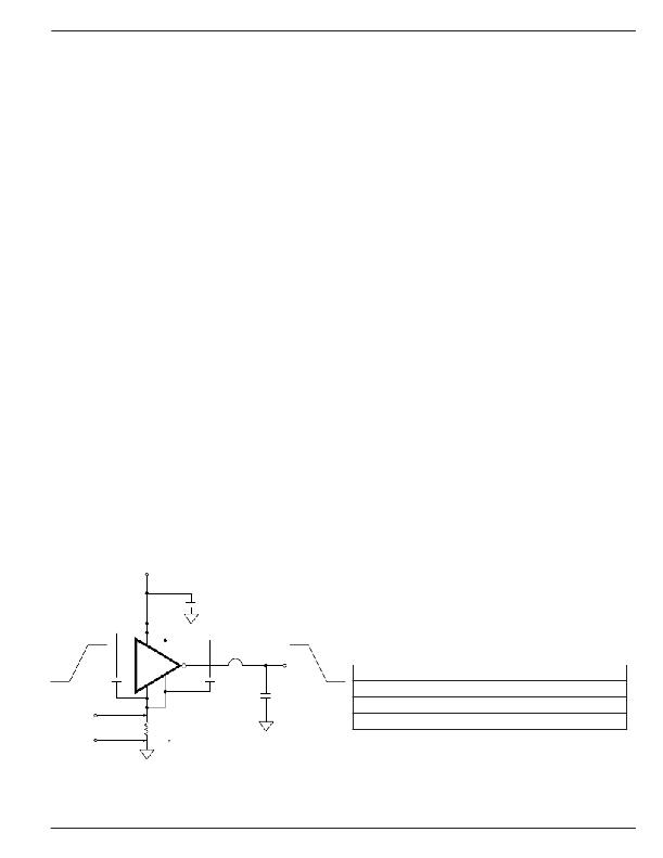
�0V�
�LOGIC�
�GROUND�
�5.0V�
�0.1μ� F�
�1�
�8�
�MIC4121�
�5�
�4�
�6� AMPS�
�6,� 7�
�TEK� CURREN� T�
�P� ROBE� 6� 3� 0� 2�
�0.1μF�
�18� V�
�0V�
�2,500� pF�
�POLYCARBONATE�
�Table� 1:� MIC4129� Maximum�
�Operating� Frequency�
�V� S�
�20V�
�15V�
�10V�
�Max� Frequency�
�1MHz�
�1.5MHz�
�3.5MHz�
�POWER�
�GROUND�
�PC� TRACE� RESISTANCE� =� 0.05� ?�
�Conditions:�
�T� A� =� 25°C,� 3.� C� L� =� 2500pF�
�Figure� 3.� Switching� Time� Degradation� Due� to�
�Negative� Feedback�
�July� 2010�
�7�
�M9999-072010�
�相关PDF资料 |
PDF描述 |
|---|---|
| MIC4223YM | IC MOSFET DVR DUAL-INV 4A 8-SOIC |
| MIC4417YM4 TR | IC DRIVER MOSF LOW SIDE SOT143-4 |
| MIC4420ZT | IC DRIVER MOSFET 6A LS TO-220-5 |
| MIC4422AYN | IC DRIVER MOSFET 9A LS 8-DIP |
| MIC4422ZT | IC DRIVER MOSFET 9A LS TO-220-5 |
相关代理商/技术参数 |
参数描述 |
|---|---|
| MIC4129YME TR | 功能描述:功率驱动器IC Improved 6A Hi-Speed, Hi-Current Single MOSFET Driver (Inverting) (Pb-Free) RoHS:否 制造商:Micrel 产品:MOSFET Gate Drivers 类型:Low Cost High or Low Side MOSFET Driver 上升时间: 下降时间: 电源电压-最大:30 V 电源电压-最小:2.75 V 电源电流: 最大功率耗散: 最大工作温度:+ 85 C 安装风格:SMD/SMT 封装 / 箱体:SOIC-8 封装:Tube |
| MIC4129YML | 制造商:MICREL 制造商全称:Micrel Semiconductor 功能描述:6A-Peak Low-Side MOSFET Driver |
| MIC4129YML TR | 功能描述:功率驱动器IC Improved 6A Hi-Speed, Hi-Current Single MOSFET Driver (Inverting) (Pb-Free) RoHS:否 制造商:Micrel 产品:MOSFET Gate Drivers 类型:Low Cost High or Low Side MOSFET Driver 上升时间: 下降时间: 电源电压-最大:30 V 电源电压-最小:2.75 V 电源电流: 最大功率耗散: 最大工作温度:+ 85 C 安装风格:SMD/SMT 封装 / 箱体:SOIC-8 封装:Tube |
| MIC4129YML-TR | 功能描述:IC DRIVER MOSFET 6A INVERT 8-MLF 制造商:microchip technology 系列:- 包装:剪切带(CT) 零件状态:有效 驱动配置:低压侧 通道类型:单路 驱动器数:1 栅极类型:N 沟道,P 沟道 MOSFET 电压 - 电源:4.5 V ~ 20 V 逻辑电压?- VIL,VIH:0.8V,2.4V 电流 - 峰值输出(灌入,拉出):6A,6A 输入类型:反相 高压侧电压 - 最大值(自举):- 上升/下降时间(典型值):12ns,13ns 工作温度:-40°C ~ 125°C (TJ) 安装类型:表面贴装 封装/外壳:8-VFDFN 裸露焊盘,8-MLF? 供应商器件封装:8-MLF?(2x2) 标准包装:1 |
| MIC4223 | 制造商:MICREL 制造商全称:Micrel Semiconductor 功能描述:Dual 4A, 4.5V to 18V, 15ns Switch Time, Low-Side MOSFET Drivers with Enable |
发布紧急采购,3分钟左右您将得到回复。