- 您现在的位置:买卖IC网 > Datasheet目录343 > MIC4420ZT (Micrel Inc)IC DRIVER MOSFET 6A LS TO-220-5 Datasheet资料下载
参数资料
| 型号: | MIC4420ZT |
| 厂商: | Micrel Inc |
| 文件页数: | 8/12页 |
| 文件大小: | 0K |
| 描述: | IC DRIVER MOSFET 6A LS TO-220-5 |
| 标准包装: | 50 |
| 配置: | 低端 |
| 输入类型: | 非反相 |
| 延迟时间: | 18ns |
| 电流 - 峰: | 6A |
| 配置数: | 1 |
| 输出数: | 1 |
| 电源电压: | 4.5 V ~ 18 V |
| 工作温度: | 0°C ~ 70°C |
| 安装类型: | 通孔 |
| 封装/外壳: | TO-220-5 |
| 供应商设备封装: | TO-220-5 |
| 包装: | 管件 |
| 产品目录页面: | 1109 (CN2011-ZH PDF) |
| 其它名称: | 576-2315 MIC4420ZT-ND |
�� �
�
�MIC4420/4429�
�Input� Stage�
�The� input� voltage� level� of� the� 4429� changes� the� quiescent�
�supply� current.� The� N� channel� MOSFET� input� stage� tran-�
�sistor� drives� a� 450μA� current� source� load.� With� a� logic� “1”�
�input,� the� maximum� quiescent� supply� current� is� 450μA.�
�Logic� “0”� input� level� signals� reduce� quiescent� current� to�
�55μA� maximum.�
�The� MIC4420/4429� input� is� designed� to� provide� 300mV� of�
�hysteresis.� This� provides� clean� transitions,� reduces� noise�
�sensitivity,� and� minimizes� output� stage� current� spiking� when�
�changing� states.� Input� voltage� threshold� level� is� approxi-�
�mately� 1.5V,� making� the� device� TTL� compatible� over� the�
�4� .5V� to� 18V� operating� supply� voltage� range.� Input� current�
�is� less� than� 10μA� over� this� range.�
�The� MIC4429� can� be� directly� driven� by� the� TL494,�
�SG1526/1527,� SG1524,� TSC170,� MIC38HC42� and� similar�
�switch� mode� power� supply� integrated� circuits.� By� of?oading�
�the� power-driving� duties� to� the� MIC4420/4429,� the� power�
�supply� controller� can� operate� at� lower� dissipation.� This� can�
�improve� performance� and� reliability.�
�The� input� can� be� greater� than� the� +� V� S� supply,� however,�
�current� will� ?ow� into� the� input� lead.� The� propagation� delay�
�for� T� D2� will� increase� to� as� much� as� 400ns� at� room� tem-�
�perature.� The� input� currents� can� be� as� high� as� 30mA� p-p�
�(6.4mA� RMS� )� with� the� input,� 6� V� greater� than� the� supply�
�voltage.� No� damage� will� occur� to� MIC4420/4429� however,�
�and� it� will� not� latch.�
�The� input� appears� as� a� 7pF� capacitance,� and� does� not�
�change� even� if� the� input� is� driven� from� an� AC� source.� Care�
�should� be� taken� so� that� the� input� does� not� go� more� than� 5�
�volts� below� the� negative� rail.�
�Power� Dissipation�
�CMOS� circuits� usually� permit� the� user� to� ignore� power� dis-�
�sipation.� Logic� families� such� as� 4000� and� 74C� have� outputs�
�which� can� only� supply� a� few� milliamperes� of� current,� and�
�even� shorting� outputs� to� ground� will� not� force� enough� cur-�
�rent� to� destroy� the� device.� The� MIC4420/4429� on� the� other�
�hand,� can� source� or� sink� several� amperes� and� drive� large�
�capacitive� loads� at� high� frequency.� The� package� power�
�dissipation� limit� can� easily� be� exceeded.� Therefore,� some�
�+18� V�
�Micrel,� Inc.�
�attention� should� be� given� to� power� dissipation� when� driving�
�low� impedance� loads� and/or� operating� at� high� frequency.�
�The� supply� current� vs� frequency� and� supply� current� vs�
�capacitive� load� characteristic� curves� aid� in� determining�
�power� dissipation� calculations.� Table� 1� lists� the� maximum�
�safe� operating� frequency� for� several� power� supply� volt-�
�ages� when� driving� a� 2500pF� load.� More� accurate� power�
�dissipation� ?gures� can� be� obtained� by� summing� the� three�
�dissipation� sources.�
�Given� the� power� dissipation� in� the� device,� and� the� thermal�
�resistance� of� the� package,� junction� operating� temperature�
�for� any� ambient� is� easy� to� calculate.� For� example,� the�
�thermal� resistance� of� the� 8-pin� MSOP� package,� from� the�
�data� sheet,� is� 250°C/W.� In� a� 25°C� ambient,� then,� using� a�
�maximum� junction� temperature� of� 150°C,� this� package� will�
�dissipate� 500mW.�
�Accurate� power� dissipation� numbers� can� be� obtained� by�
�summing� the� three� sources� of� power� dissipation� in� the�
�device:�
�?� Load� Power� Dissipation� (P� L� )�
�?� Quiescent� power� dissipation� (P� Q� )�
�?� Transition� power� dissipation� (P� T� )�
�Calculation� of� load� power� dissipation� differs� depending� on�
�whether� the� load� is� capacitive,� resistive� or� inductive.�
�Resistive� Load� Power� Dissipation�
�Dissipation� caused� by� a� resistive� load� can� be� calculated�
�as:�
�P� L� =� I� 2� R� O� D�
�where:�
�I� =� the� current� drawn� by� the� load�
�R� O� =� the� output� resistance� of� the� driver� when� the� output�
�is� high,� at� the� power� supply� voltage� used.� (See� data�
�sheet)�
�D� =� fraction� of� time� the� load� is� conducting� (duty� cycle)�
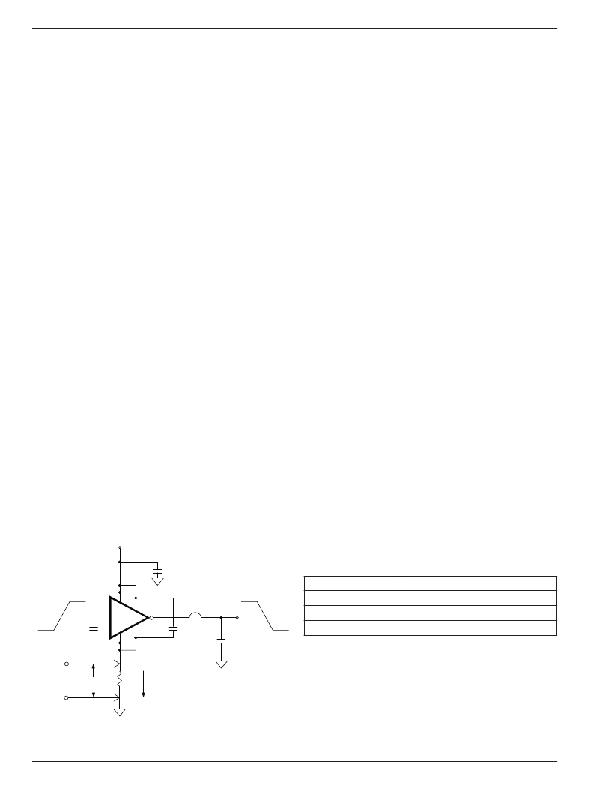
�Table� 1:� MIC4429� Maximum�
�5.0V�
�1�
�8�
�MIC4429�
�6,� 7�
�WIMA�
�MKS-2�
�1� μF�
�TE� K� C� U� R� R� E� N� T�
�P� ROB� E� 6� 3� 0� 2�
�18� V�
�Operating� Frequency�
�V� S�
�18V�
�15V�
�Max� Frequency�
�500kHz�
�700kHz�
�LOGIC�
�GROUND�
�0V�
�0.1μF�
�4�
�5�
�6� AMPS�
�0.1μF�
�0V�
�2,500� pF�
�POLYCARBONATE�
�10V�
�Conditions:�
�1.6MHz�
�1.� DIP� Package� (� θ� JA� =� 130°C/W)�
�2.� T� A� =� 25°C�
�3.� C� L� =� 2500pF�
�300� mV�
�PC� TRACE� RESISTANCE� =� 0.05?�
�POWER�
�GROUND�
�Figure� 4.� Switching� Time� Degradation� Due� to�
�Negative� Feedback�
�M9999-072205�
�8�
�July� 2005�
�相关PDF资料 |
PDF描述 |
|---|---|
| MIC4422AYN | IC DRIVER MOSFET 9A LS 8-DIP |
| MIC4422ZT | IC DRIVER MOSFET 9A LS TO-220-5 |
| MIC4424YWM | IC DRIVER MOSFET 3A DUAL 16-SOIC |
| MIC4427YM | IC DRIVER MOSFET DUAL 1.5A 8SOIC |
| MIC4451ZT | IC DRIVER MOSFET 12A HS TO220-5 |
相关代理商/技术参数 |
参数描述 |
|---|---|
| MIC4421 | 制造商:MIC 制造商全称:MIC GROUP RECTIFIERS 功能描述:9A-Peak Low-Side MOSFET Driver Bipolar/CMOS/DMOS Process |
| MIC4421_05 | 制造商:MICREL 制造商全称:Micrel Semiconductor 功能描述:9A-Peak Low-Side MOSFET Driver |
| MIC4421_11 | 制造商:MIC 制造商全称:MIC GROUP RECTIFIERS 功能描述:9A-Peak Low-Side MOSFET Driver Bipolar/CMOS/DMOS Process |
| MIC4421A | 制造商:MIC 制造商全称:MIC GROUP RECTIFIERS 功能描述:High peak-output current: 9A Peak (typ.) |
| MIC4421A_11 | 制造商:MIC 制造商全称:MIC GROUP RECTIFIERS 功能描述:High peak-output current: 9A Peak (typ.) |
发布紧急采购,3分钟左右您将得到回复。