- 您现在的位置:买卖IC网 > PDF目录382334 > MM58274CV (NATIONAL SEMICONDUCTOR CORP) Microprocessor Compatible Real Time Clock PDF资料下载
参数资料
| 型号: | MM58274CV |
| 厂商: | NATIONAL SEMICONDUCTOR CORP |
| 元件分类: | XO, clock |
| 英文描述: | Microprocessor Compatible Real Time Clock |
| 中文描述: | 0 TIMER(S), REAL TIME CLOCK, PQCC20 |
| 封装: | PLASTIC, LCC-20 |
| 文件页数: | 9/16页 |
| 文件大小: | 228K |
| 代理商: | MM58274CV |
Functional Description
(Continued)
Both of the flags and the interrupt output are reset by the
trailing edge of the read strobe. The flag information is held
latched during a control register read, guaranteeing that sta-
ble status information will always be read out by the proces-
sor.
Interrupt timeout is detected and stored internally if it occurs
during a read of the control register, the interrupt output will
then go low only after the read has been completed.
A clock setting pulse occurring during a control register read
will not affect the data-changed flag since time data read
out before or after the control read will not be affected by
the time change.
METHODS OF DEVICE OPERATION
Test Mode
National Semiconductor uses test mode for functionally
testing the MM58274C after fabrication and again after
packaging. Test mode can also be used to set up the oscil-
lator frequency when the part is first commissioned.
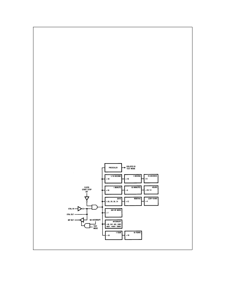
Figure 4 shows the internal clock connections when the de-
vice is written into test mode. The 32.768 kHz oscillator is
gated onto the interrupt output to provide a buffered output
for initial frequency setting. This signal is driven from a
TRI-STATE output buffer, enabling easy oscillator setting in
systems where interrupt is not normally used and there is no
external resistor on the pin.
If an interrupt is programmed, the 32.768 kHz output is
switched off to allow high speed testing of the interrupt tim-
er. The interrupt output will then function as normal.
The clock start/stop bit can be used to control the fast
clocking of the time registers as shown in Figure 4.
Initialization
When it is first installed and power is applied, the device will
need to be properly initialized. The following operation steps
are recommended when the device is set up (all numbers
are decimal):
1) Disable interrupt on the processor to allow oscillator set-
ting. Write 15
10
into the control register:The clock and inter-
rupt start/stop bits are set to 1, ensuring that the clock and
interrupt timers are both halted. Test mode and the interrupt
register are selected.
2) Write 0 to the interrupt register: Ensure that there are no
interrupts programmed and that the oscillator will be gated
onto the interrupt output.
3) Set oscillator frequency: All timing has been halted and
the oscillator is buffered out onto the interrupt line.
4) Write 5 to the control register:The clock is now out of test
mode but is still halted. The clock setting register is now
selected by the interrupt select bit.
5) Write 0001 to all registers. This ensures starting with a
valid BCD value in each register.
6) Set 12/24 Hours Mode:Write to the clock setting register
to select the hours counting mode required.
7) Load Real-Time Registers: All time registers (including
Leap Years and AM/PM bit) may now be loaded in any
order. Note that when writing to the clock setting register to
set up Leap Years and AM/PM, the Hours Mode bit must
not be altered from the value programmed in step 5.
8) Write 0 to the control register:This operation finishes the
clock initialization by starting the time. The final control reg-
ister write should be synchronized with an external time
source.
In general, timekeeping should be halted before the time
data is altered in the clock. The data can, however, be al-
tered at any time if so desired. Such may be the case if the
user wishes to keep the clock corrected without having to
stop and restart it; i.e., winter/summer time changing can be
accomplished without halting the clock. This can be done in
software by sensing the state of the data-changed flag and
only altering time data just after the time has rolled over
(data-changed flag set).
TL/F/11219–7
FIGURE 4. Test Mode Organization
9
相关PDF资料 |
PDF描述 |
|---|---|
| MM58341 | High Voltage Display Driver |
| MM58341N | High Voltage Display Driver |
| MM58341V | High Voltage Display Driver |
| MM58342 | MM58342 High Voltage Display Driver |
| MM58342N | MM58342 High Voltage Display Driver |
相关代理商/技术参数 |
参数描述 |
|---|---|
| MM58274CV-12 | 制造商:NSC 制造商全称:National Semiconductor 功能描述:MICROPROCESSOR COMPATIBLE REAL TIME CLOCK |
| MM5829-2600RB8 | 制造商:MURATA-PS 制造商全称:Murata Power Solutions Inc. 功能描述:Coaxial Connectors (Chip Type Receptacle) |
| MM5829-2700RJ4 | 功能描述:RF 连接器 12GHz 0.035ohm JSC Type Connector RoHS:否 制造商:Bomar Interconnect 产品:Connectors 射频系列:BNC 型式:Jack (Female) 极性: 触点电镀:Gold 阻抗: 端接类型:Solder 主体类型:Straight Bulkhead 电缆类型: |
| MM5829-2700RK0 | 功能描述:RF 连接器 12GHz 0.035ohm JSC Type Connector RoHS:否 制造商:Bomar Interconnect 产品:Connectors 射频系列:BNC 型式:Jack (Female) 极性: 触点电镀:Gold 阻抗: 端接类型:Solder 主体类型:Straight Bulkhead 电缆类型: |
| MM58341 | 制造商:NSC 制造商全称:National Semiconductor 功能描述:High Voltage Display Driver |
发布紧急采购,3分钟左右您将得到回复。