- 您现在的位置:买卖IC网 > PDF目录95995 > MPC990/D (FREESCALE SEMICONDUCTOR INC) OTHER CLOCK GENERATOR, PQFP52 PDF资料下载
参数资料
| 型号: | MPC990/D |
| 厂商: | FREESCALE SEMICONDUCTOR INC |
| 元件分类: | 时钟产生/分配 |
| 英文描述: | OTHER CLOCK GENERATOR, PQFP52 |
| 封装: | TQFP-52 |
| 文件页数: | 1/7页 |
| 文件大小: | 324K |
| 代理商: | MPC990/D |
Order Number: MPC990/D
MOTOROLA
SEMICONDUCTOR TECHNICAL DATA
Rev 4, 09/2001
MOTOROLA ADVANCED CLOCK DRIVERS DEVICE DATA
263
Low Voltage PLL Clock
Driver
The MPC990 is a 3.3 V compatible, PLL based clock driver. The fully
differential design ensures optimum skew and PLL jitter performance.
The performance of the MPC990 makes the device ideal for Workstation,
Mainframe Computer and Telecommunication applications. The MPC990
offers an on–board crystal oscillator as the PLL reference and offers a
secondary single–ended ECL clock for system test capabilities.
Fully Integrated PLL
Output Frequency Up to 400 MHz
Operates from a 3.3 V Supply
Output Frequency Configurable
TQFP Packaging
±50 ps Cycle–to–Cycle Jitter
The MPC990 offers three banks of outputs which can each be
programmed via the the four fsel pins of the device. There are 16 different
output frequency configurations available in the device. The configura-
tions include output ratios of 1:1, 2:1, 3:1, 3:2, 4:1, 4:3, 4:3:1 and 4:3:2.
The programming table in this data sheet illustrates the various
programming options. The SYNC output monitors the relationship
between the Qa and Qc output banks. The output pulses per the timing
diagrams in this data sheet signal the coincident edges of the two output
banks. This feature is useful for non binary relationships between output
frequencies (i.e., 3:2 or 4:3 relationships). The Sync_Sel input toggles the
Qd outputs between sync signals and extensions to the Qc bank of
outputs.
The MPC990 provides a separate output for the feedback to the PLL. This allows for the feedback frequency to be pro-
grammed independently of the other outputs allowing for unique input vs output frequency relationships. The fselFB inputs pro-
vide 6 different feedback frequencies from the QFB differential output pair. The MPC990 features an external feedback to the
PLL.
The PLL_En, Ref_Sel and the Test_Clk input pins provide a means of bypassing the PLL and driving the output buffers direct-
ly. This allows the user to single step a design during system debug. Note that the Test_Clk input is routed through the dividers
so that, depending on the programming, several edges on the Test_Clk input will be needed to get corresponding edge transi-
tions on the outputs. The VCO_Sel input provides a means of recentering the VCO to provide a broader range of VCO frequen-
cies for stable PLL operation.
If the frequency select or the VCO_Sel pins are changed during operation, a master reset signal must be applied to ensure
output synchronization and phase–lock. If the VCO is driven beyond its maximum frequency, the VCO can outrun the internal
dividers when the VCO_Sel pin is low. This will also prevent the PLL from achieving lock. Again, a master reset signal will need
to be applied to allow for phase–lock. The device employs a power–on reset circuit which will ensure output synchronization and
PLL lock on initial power–up.
Rev 4
2
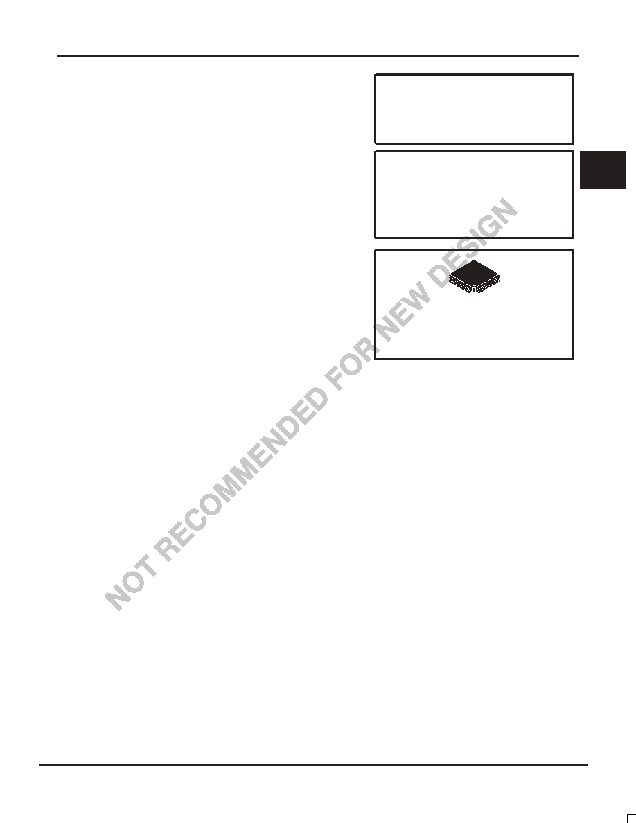
MPC990
LOW VOLTAGE
PLL CLOCK DRIVER
FA SUFFIX
52–LEAD TQFP PACKAGE
CASE 848D–03
F
re
e
sc
a
le
S
e
m
ic
o
n
d
u
c
to
r,
I
Freescale Semiconductor, Inc.
For More Information On This Product,
Go to: www.freescale.com
n
c
..
.
相关PDF资料 |
PDF描述 |
|---|---|
| MPC990FA | 400 MHz, PROC SPECIFIC CLOCK GENERATOR, PQFP52 |
| MPC992FA | 375 MHz, PROC SPECIFIC CLOCK GENERATOR, PQFP32 |
| MPD400 | SILICON, STABISTOR DIODE |
| MPE-24H | 15 A, SILICON, RECTIFIER DIODE, TO-220AB |
| MPF102D74Z | Si, N-CHANNEL, RF SMALL SIGNAL, JFET, TO-92 |
相关代理商/技术参数 |
参数描述 |
|---|---|
| MPC990F18 F44A WAF | 制造商:Motorola Inc 功能描述: |
| MPC991 | 制造商:MOTOROLA 制造商全称:Motorola, Inc 功能描述:LOW VOLTAGE PLL CLOCK DRIVER |
| MPC991FA | 制造商:Motorola Inc 功能描述: |
| MPC992 | 制造商:MOTOROLA 制造商全称:Motorola, Inc 功能描述:LOW VOLTAGE PLL CLOCK DRIVER |
| MPC992D33 F44A WAF | 制造商:Motorola Inc 功能描述: |
发布紧急采购,3分钟左右您将得到回复。