- 您现在的位置:买卖IC网 > PDF目录11973 > MSP430F4794IPZR (Texas Instruments)IC MCU 16BIT 60KB FLASH 100LQFP PDF资料下载
参数资料
| 型号: | MSP430F4794IPZR |
| 厂商: | Texas Instruments |
| 文件页数: | 30/80页 |
| 文件大小: | 0K |
| 描述: | IC MCU 16BIT 60KB FLASH 100LQFP |
| 产品培训模块: | The Ultra-Low Power MSP430 MSP430 Overview MSP430 Design Tools MSP430 Peripherals MSP430x2xx/4xx and Wireless Overview Portable Medical Solutions with MSP430 MSP430 for Utility Metering Solutions MSP430: How to JTAG MSP430, How To Use the Clock System Grace Software Graphical User Interface MCU Overview Driver Library MSP430Ware Overview |
| 标准包装: | 1 |
| 系列: | MSP430x4xx |
| 核心处理器: | RISC |
| 芯体尺寸: | 16-位 |
| 速度: | 16MHz |
| 连通性: | I²C,IrDA,LIN,SCI,SPI,UART/USART |
| 外围设备: | 欠压检测/复位,LCD,POR,PWM,WDT |
| 输入/输出数: | 72 |
| 程序存储器容量: | 60KB(60K x 8 + 256B) |
| 程序存储器类型: | 闪存 |
| RAM 容量: | 2.5K x 8 |
| 电压 - 电源 (Vcc/Vdd): | 1.8 V ~ 3.6 V |
| 数据转换器: | A/D 4x16b |
| 振荡器型: | 内部 |
| 工作温度: | -40°C ~ 85°C |
| 封装/外壳: | 100-LQFP |
| 包装: | 标准包装 |
| 产品目录页面: | 714 (CN2011-ZH PDF) |
| 其它名称: | 296-24722-6 |
第1页第2页第3页第4页第5页第6页第7页第8页第9页第10页第11页第12页第13页第14页第15页第16页第17页第18页第19页第20页第21页第22页第23页第24页第25页第26页第27页第28页第29页当前第30页第31页第32页第33页第34页第35页第36页第37页第38页第39页第40页第41页第42页第43页第44页第45页第46页第47页第48页第49页第50页第51页第52页第53页第54页第55页第56页第57页第58页第59页第60页第61页第62页第63页第64页第65页第66页第67页第68页第69页第70页第71页第72页第73页第74页第75页第76页第77页第78页第79页第80页
MSP430F47x3, MSP430F47x4
MIXED SIGNAL MICROCONTROLLER
SLAS545C MAY 2007 REVISED MARCH 2011
36
POST OFFICE BOX 655303
DALLAS, TEXAS 75265
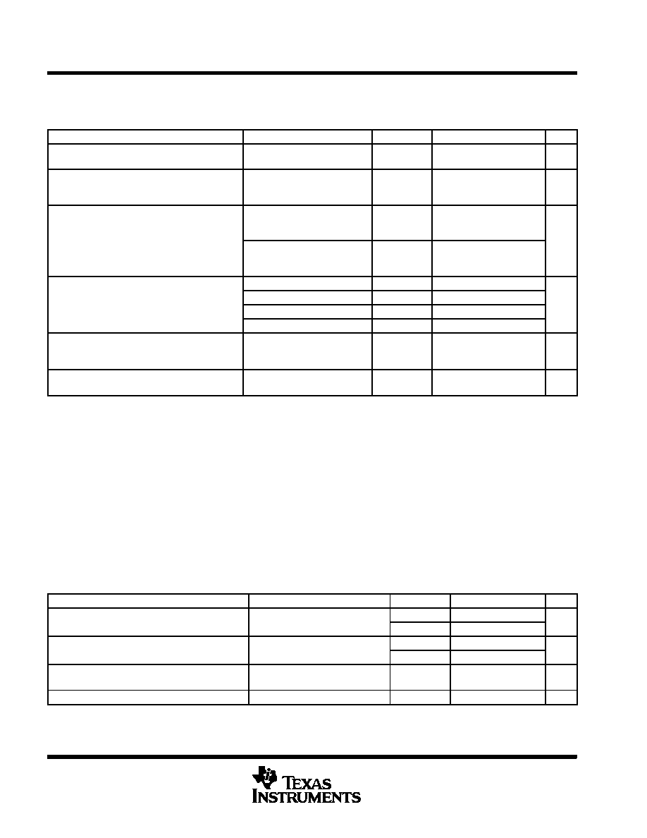
electrical characteristics over recommended operating free-air temperature (unless otherwise
noted) (continued)
crystal oscillator, LFXT1, low-frequency modes (see Note 4)
PARAMETER
TEST CONDITIONS
VCC
MIN
TYP
MAX
UNIT
fLFXT1, LF
LFXT1 oscillator crystal
frequency, LF mode
XTS_FLL = 0, LFXT1DIG = 0
1.8 V3.6 V
32, 768
Hz
fLFXT1, LF, logic
LFXT1 oscillator logic level
square-wave input frequency,
LF mode
XTS_FLL = 0, LFXT1DIG = 1,
XCAPx = 0
1.8 V3.6 V
10, 000
32, 768
Hz
OA
Oscillation allowance for LF
XTS_FLL = 0, LFXT1DIG = 0,
fLFXT1, LF = 32,768 kHz,
CL, eff = 6 pF
500
k
W
OALF
Oscillation allowance for LF
crystals
XTS_FLL = 0, LFXT1DIG = 0,
fLFXT1, LF = 32,768 kHz,
CL, eff = 12 pF
200
k
W
XTS_FLL = 0, XCAPx = 0
1
C
Integrated effective load
capacitance LF mode
XTS_FLL = 0, XCAPx = 1
5.5
pF
CL, eff
capacitance, LF mode
(see Note 1)
XTS_FLL = 0, XCAPx = 2
8.5
pF
(see Note 1)
XTS_FLL = 0, XCAPx = 3
11
Duty Cycle
LF mode
XTS_FLL = 0,
Measured at P1.4/ACLK,
fLFXT1, LF = 32, 768 Hz
2.2 V/3 V
30
50
70
%
fFault, LF
Oscillator fault frequency,
LF mode (see Note 3)
XTS_FLL = 0 (see Note 2)
2.2 V/3 V
10
10, 000
Hz
NOTES:
1. Includes parasitic bond and package capacitance (approximately 2pF per pin).
Since the PCB adds additional capacitance it is recommended to verify the correct load by measuring the ACLK frequency. For a
correct setup the effective load capacitance should always match the specification of the used crystal.
2. Measured with logic level input frequency but also applies to operation with crystals.
3. Frequencies below the MIN specification will set the fault flag, frequencies above the MAX specification will not set the fault flag.
Frequencies in between might set the flag.
4. To improve EMI on the LFXT1 oscillator the following guidelines should be observed.
Keep as short of a trace as possible between the device and the crystal.
Design a good ground plane around the oscillator pins.
Prevent crosstalk from other clock or data lines into oscillator pins XIN and XOUT.
Avoid running PCB traces underneath or adjacent to the XIN and XOUT pins.
Use assembly materials and praxis to avoid any parasitic load on the oscillator XIN and XOUT pins.
If conformal coating is used, ensure that it does not induce capacitive/resistive leakage between the oscillator pins.
Do not route the XOUT line to the JTAG header to support the serial programming adapter as shown in other
documentation. This signal is no longer required for the serial programming adapter.
crystal oscillator, LFXT1, high-frequency mode
PARAMETER
TEST CONDITIONS
VCC
MIN
TYP
MAX
UNIT
f
XT1 oscillator crystal frequency
XTS FLL
1 Ceramic resonator
1.8 V3.6 V
0.45
4
MHz
fXT1
XT1 oscillator crystal frequency
XTS_FLL = 1, Ceramic resonator
2.7 V3.6 V
0.45
8
MHz
f
XT1 oscillator crystal frequency
XTS FLL
1 Crystal
1.8 V3.6 V
1
4
MHz
fXT1
XT1 oscillator crystal frequency
XTS_FLL = 1, Crystal
2.7 V3.6 V
1
8
MHz
CL, eff
Integrated effective Load
Capacitance (see Note 1)
XTS_FLL = 1, XCAPx = 0
(see Note 2)
1
pF
Duty Cycle
Measured at P1.4/ACLK
2.2 V/3 V
40
50
60
%
NOTES:
1. Includes parasitic bond and package capacitance (approximately 2pF per pin).
Since the PCB adds additional capacitance it is recommended to verify the correct load by measuring the ACLK frequency. For a
correct setup the effective load capacitance should always match the specification of the used crystal.
2. Requires external capacitors at both terminals. Values are specified by crystal manufacturers.
相关PDF资料 |
PDF描述 |
|---|---|
| VI-B6N-CU-B1 | CONVERTER MOD DC/DC 18.5V 200W |
| 6278807-8 | MTRJ KEYED JACK KIT 6PCK VIOLT |
| 6278807-7 | MTRJ KEYED JACK KIT 6PCK BROWN |
| 6278807-6 | MTRJ KEYED JACK KIT 6PCK AQUA |
| MC908EY8CFAE | IC MCU 8K FLASH 8MHZ 32-LQFP |
相关代理商/技术参数 |
参数描述 |
|---|---|
| MSP430F479IPN | 功能描述:16位微控制器 - MCU 16B Ultra-Lo-Pwr MCU 32KB Fl 2KB RAM RoHS:否 制造商:Texas Instruments 核心:RISC 处理器系列:MSP430FR572x 数据总线宽度:16 bit 最大时钟频率:24 MHz 程序存储器大小:8 KB 数据 RAM 大小:1 KB 片上 ADC:Yes 工作电源电压:2 V to 3.6 V 工作温度范围:- 40 C to + 85 C 封装 / 箱体:VQFN-40 安装风格:SMD/SMT |
| MSP430F479IPNR | 功能描述:16位微控制器 - MCU 16B Ultra-Lo-Pwr MCU 32KB Fl 2KB RAM RoHS:否 制造商:Texas Instruments 核心:RISC 处理器系列:MSP430FR572x 数据总线宽度:16 bit 最大时钟频率:24 MHz 程序存储器大小:8 KB 数据 RAM 大小:1 KB 片上 ADC:Yes 工作电源电压:2 V to 3.6 V 工作温度范围:- 40 C to + 85 C 封装 / 箱体:VQFN-40 安装风格:SMD/SMT |
| MSP430F479IZQW | 功能描述:16位微控制器 - MCU 16B Ultra-Lo-Pwr MCU 32KB Fl 2KB RAM RoHS:否 制造商:Texas Instruments 核心:RISC 处理器系列:MSP430FR572x 数据总线宽度:16 bit 最大时钟频率:24 MHz 程序存储器大小:8 KB 数据 RAM 大小:1 KB 片上 ADC:Yes 工作电源电压:2 V to 3.6 V 工作温度范围:- 40 C to + 85 C 封装 / 箱体:VQFN-40 安装风格:SMD/SMT |
| MSP430F479IZQWR | 功能描述:16位微控制器 - MCU 16B Ultra-Lo-Pwr MCU 32KB Fl 2KB RAM RoHS:否 制造商:Texas Instruments 核心:RISC 处理器系列:MSP430FR572x 数据总线宽度:16 bit 最大时钟频率:24 MHz 程序存储器大小:8 KB 数据 RAM 大小:1 KB 片上 ADC:Yes 工作电源电压:2 V to 3.6 V 工作温度范围:- 40 C to + 85 C 封装 / 箱体:VQFN-40 安装风格:SMD/SMT |
| MSP430F5131IDA | 功能描述:16位微控制器 - MCU MIXED SIGNAL MCU RoHS:否 制造商:Texas Instruments 核心:RISC 处理器系列:MSP430FR572x 数据总线宽度:16 bit 最大时钟频率:24 MHz 程序存储器大小:8 KB 数据 RAM 大小:1 KB 片上 ADC:Yes 工作电源电压:2 V to 3.6 V 工作温度范围:- 40 C to + 85 C 封装 / 箱体:VQFN-40 安装风格:SMD/SMT |
发布紧急采购,3分钟左右您将得到回复。