- 您现在的位置:买卖IC网 > PDF目录80528 > MSP430F5633IPZ (TEXAS INSTRUMENTS INC) 16-BIT, FLASH, 20 MHz, RISC MICROCONTROLLER, PQFP100 PDF资料下载
参数资料
| 型号: | MSP430F5633IPZ |
| 厂商: | TEXAS INSTRUMENTS INC |
| 元件分类: | 微控制器/微处理器 |
| 英文描述: | 16-BIT, FLASH, 20 MHz, RISC MICROCONTROLLER, PQFP100 |
| 封装: | GREEN, PLASTIC, LQFP-100 |
| 文件页数: | 44/101页 |
| 文件大小: | 1073K |
| 代理商: | MSP430F5633IPZ |
第1页第2页第3页第4页第5页第6页第7页第8页第9页第10页第11页第12页第13页第14页第15页第16页第17页第18页第19页第20页第21页第22页第23页第24页第25页第26页第27页第28页第29页第30页第31页第32页第33页第34页第35页第36页第37页第38页第39页第40页第41页第42页第43页当前第44页第45页第46页第47页第48页第49页第50页第51页第52页第53页第54页第55页第56页第57页第58页第59页第60页第61页第62页第63页第64页第65页第66页第67页第68页第69页第70页第71页第72页第73页第74页第75页第76页第77页第78页第79页第80页第81页第82页第83页第84页第85页第86页第87页第88页第89页第90页第91页第92页第93页第94页第95页第96页第97页第98页第99页第100页第101页
PRODUCTPREVIEW
MSP430F563x
www.ti.com
SLAS650A – JUNE 2010 – REVISED JULY 2010
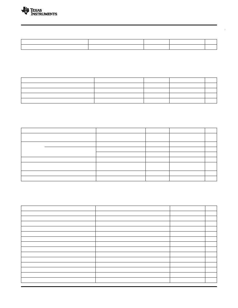
Crystal Oscillator, XT2 (continued)
over recommended ranges of supply voltage and operating free-air temperature (unless otherwise noted)
PARAMETER
TEST CONDITIONS
VCC
MIN
TYP
MAX
UNIT
fFault,HF
Oscillator fault frequency(7)
XT2BYPASS = 1(8)
30
300
kHz
(7)
Frequencies below the MIN specification set the fault flag. Frequencies above the MAX specification do not set the fault flag.
Frequencies in between might set the flag.
(8)
Measured with logic-level input frequency but also applies to operation with crystals.
Internal Very-Low-Power Low-Frequency Oscillator (VLO)
over recommended ranges of supply voltage and operating free-air temperature (unless otherwise noted)
PARAMETER
TEST CONDITIONS
VCC
MIN
TYP
MAX
UNIT
fVLO
VLO frequency
Measured at ACLK
1.8 V to 3.6 V
6
9.4
14
kHz
dfVLO/dT
VLO frequency temperature drift
Measured at ACLK(1)
1.8 V to 3.6 V
0.5
%/°C
dfVLO/dVCC VLO frequency supply voltage drift
Measured at ACLK(2)
1.8 V to 3.6 V
4
%/V
Duty cycle
Measured at ACLK
1.8 V to 3.6 V
40
50
60
%
(1)
Calculated using the box method: (MAX(-40 to 85°C) – MIN(-40 to 85°C)) / MIN(-40 to 85°C) / (85°C – (–40°C))
(2)
Calculated using the box method: (MAX(1.8 to 3.6 V) – MIN(1.8 to 3.6 V)) / MIN(1.8 to 3.6 V) / (3.6 V – 1.8 V)
Internal Reference, Low-Frequency Oscillator (REFO)
over recommended ranges of supply voltage and operating free-air temperature (unless otherwise noted)
PARAMETER
TEST CONDITIONS
VCC
MIN
TYP
MAX
UNIT
REFO oscillator current
IREFO
TA = 25°C
1.8 V to 3.6 V
3
A
consumption
REFO frequency calibrated
Measured at ACLK
1.8 V to 3.6 V
32768
Hz
fREFO
Full temperature range
1.8 V to 3.6 V
±3.5
%
REFO absolute tolerance
calibrated
TA = 25°C
3 V
±1.5
%
dfREFO/dT
REFO frequency temperature drift
Measured at ACLK(1)
1.8 V to 3.6 V
0.01
%/°C
REFO frequency supply voltage
dfREFO/dVCC
Measured at ACLK(2)
1.8 V to 3.6 V
1.0
%/V
drift
Duty cycle
Measured at ACLK
1.8 V to 3.6 V
40
50
60
%
tSTART
REFO startup time
40%/60% duty cycle
1.8 V to 3.6 V
25
s
(1)
Calculated using the box method: (MAX(-40 to 85°C) – MIN(-40 to 85°C)) / MIN(-40 to 85°C) / (85°C – (–40°C))
(2)
Calculated using the box method: (MAX(1.8 to 3.6 V) – MIN(1.8 to 3.6 V)) / MIN(1.8 to 3.6 V) / (3.6 V – 1.8 V)
DCO Frequency
over recommended ranges of supply voltage and operating free-air temperature (unless otherwise noted)
PARAMETER
TEST CONDITIONS
MIN
TYP
MAX
UNIT
fDCO(0,0)
DCO frequency (0, 0)
DCORSELx = 0, DCOx = 0, MODx = 0
0.07
0.20
MHz
fDCO(0,31)
DCO frequency (0, 31)
DCORSELx = 0, DCOx = 31, MODx = 0
0.70
1.70
MHz
fDCO(1,0)
DCO frequency (1, 0)
DCORSELx = 1, DCOx = 0, MODx = 0
0.15
0.36
MHz
fDCO(1,31)
DCO frequency (1, 31)
DCORSELx = 1, DCOx = 31, MODx = 0
1.47
3.45
MHz
fDCO(2,0)
DCO frequency (2, 0)
DCORSELx = 2, DCOx = 0, MODx = 0
0.32
0.75
MHz
fDCO(2,31)
DCO frequency (2, 31)
DCORSELx = 2, DCOx = 31, MODx = 0
3.17
7.38
MHz
fDCO(3,0)
DCO frequency (3, 0)
DCORSELx = 3, DCOx = 0, MODx = 0
0.64
1.51
MHz
fDCO(3,31)
DCO frequency (3, 31)
DCORSELx = 3, DCOx = 31, MODx = 0
6.07
14.0
MHz
fDCO(4,0)
DCO frequency (4, 0)
DCORSELx = 4, DCOx = 0, MODx = 0
1.3
3.2
MHz
fDCO(4,31)
DCO frequency (4, 31)
DCORSELx = 4, DCOx = 31, MODx = 0
12.3
28.2
MHz
fDCO(5,0)
DCO frequency (5, 0)
DCORSELx = 5, DCOx = 0, MODx = 0
2.5
6.0
MHz
fDCO(5,31)
DCO frequency (5, 31)
DCORSELx = 5, DCOx = 31, MODx = 0
23.7
54.1
MHz
fDCO(6,0)
DCO frequency (6, 0)
DCORSELx = 6, DCOx = 0, MODx = 0
4.6
10.7
MHz
fDCO(6,31)
DCO frequency (6, 31)
DCORSELx = 6, DCOx = 31, MODx = 0
39.0
88.0
MHz
Copyright 2010, Texas Instruments Incorporated
47
相关PDF资料 |
PDF描述 |
|---|---|
| MB95F118MWPMC | 8-BIT, FLASH, 16.25 MHz, MICROCONTROLLER, PQFP52 |
| M30245M8-XXXGP | 16-BIT, MROM, 16 MHz, MICROCONTROLLER, PQFP100 |
| M30281F6HP-U7 | 16-BIT, FLASH, 20 MHz, MICROCONTROLLER, PQFP64 |
| M30290FCHP-U5 | 16-BIT, FLASH, 20 MHz, MICROCONTROLLER, PQFP80 |
| M30621FCAGP | 16-BIT, FLASH, 16 MHz, MICROCONTROLLER, PQFP80 |
相关代理商/技术参数 |
参数描述 |
|---|---|
| MSP430F5633IPZR | 功能描述:16位微控制器 - MCU Mixed Signal MCU RoHS:否 制造商:Texas Instruments 核心:RISC 处理器系列:MSP430FR572x 数据总线宽度:16 bit 最大时钟频率:24 MHz 程序存储器大小:8 KB 数据 RAM 大小:1 KB 片上 ADC:Yes 工作电源电压:2 V to 3.6 V 工作温度范围:- 40 C to + 85 C 封装 / 箱体:VQFN-40 安装风格:SMD/SMT |
| MSP430F5633IZQWR | 功能描述:16位微控制器 - MCU Mixed Signal MCU RoHS:否 制造商:Texas Instruments 核心:RISC 处理器系列:MSP430FR572x 数据总线宽度:16 bit 最大时钟频率:24 MHz 程序存储器大小:8 KB 数据 RAM 大小:1 KB 片上 ADC:Yes 工作电源电压:2 V to 3.6 V 工作温度范围:- 40 C to + 85 C 封装 / 箱体:VQFN-40 安装风格:SMD/SMT |
| MSP430F5633IZQWT | 制造商:Texas Instruments 功能描述:IC MCU 16BIT 128KB FLASH 113BGA 制造商:Texas Instruments 功能描述:Ultra low power Micro Controller |
| MSP430F5634IPZ | 功能描述:16位微控制器 - MCU Mixed Signal MCU RoHS:否 制造商:Texas Instruments 核心:RISC 处理器系列:MSP430FR572x 数据总线宽度:16 bit 最大时钟频率:24 MHz 程序存储器大小:8 KB 数据 RAM 大小:1 KB 片上 ADC:Yes 工作电源电压:2 V to 3.6 V 工作温度范围:- 40 C to + 85 C 封装 / 箱体:VQFN-40 安装风格:SMD/SMT |
| MSP430F5634IPZR | 功能描述:16位微控制器 - MCU Mixed Signal MCU RoHS:否 制造商:Texas Instruments 核心:RISC 处理器系列:MSP430FR572x 数据总线宽度:16 bit 最大时钟频率:24 MHz 程序存储器大小:8 KB 数据 RAM 大小:1 KB 片上 ADC:Yes 工作电源电压:2 V to 3.6 V 工作温度范围:- 40 C to + 85 C 封装 / 箱体:VQFN-40 安装风格:SMD/SMT |
发布紧急采购,3分钟左右您将得到回复。