- 您现在的位置:买卖IC网 > PDF目录80580 > MSX340-10PB480 DSP-CROSSBAR SWITCH, PBGA480 PDF资料下载
参数资料
| 型号: | MSX340-10PB480 |
| 元件分类: | 数字信号处理外设 |
| 英文描述: | DSP-CROSSBAR SWITCH, PBGA480 |
| 封装: | BGA-480 |
| 文件页数: | 9/61页 |
| 文件大小: | 1443K |
| 代理商: | MSX340-10PB480 |
第1页第2页第3页第4页第5页第6页第7页第8页当前第9页第10页第11页第12页第13页第14页第15页第16页第17页第18页第19页第20页第21页第22页第23页第24页第25页第26页第27页第28页第29页第30页第31页第32页第33页第34页第35页第36页第37页第38页第39页第40页第41页第42页第43页第44页第45页第46页第47页第48页第49页第50页第51页第52页第53页第54页第55页第56页第57页第58页第59页第60页第61页
MSX Family Data Sheet
I-Cube, Inc.
[Rev. 1.8] 2/28/01
17
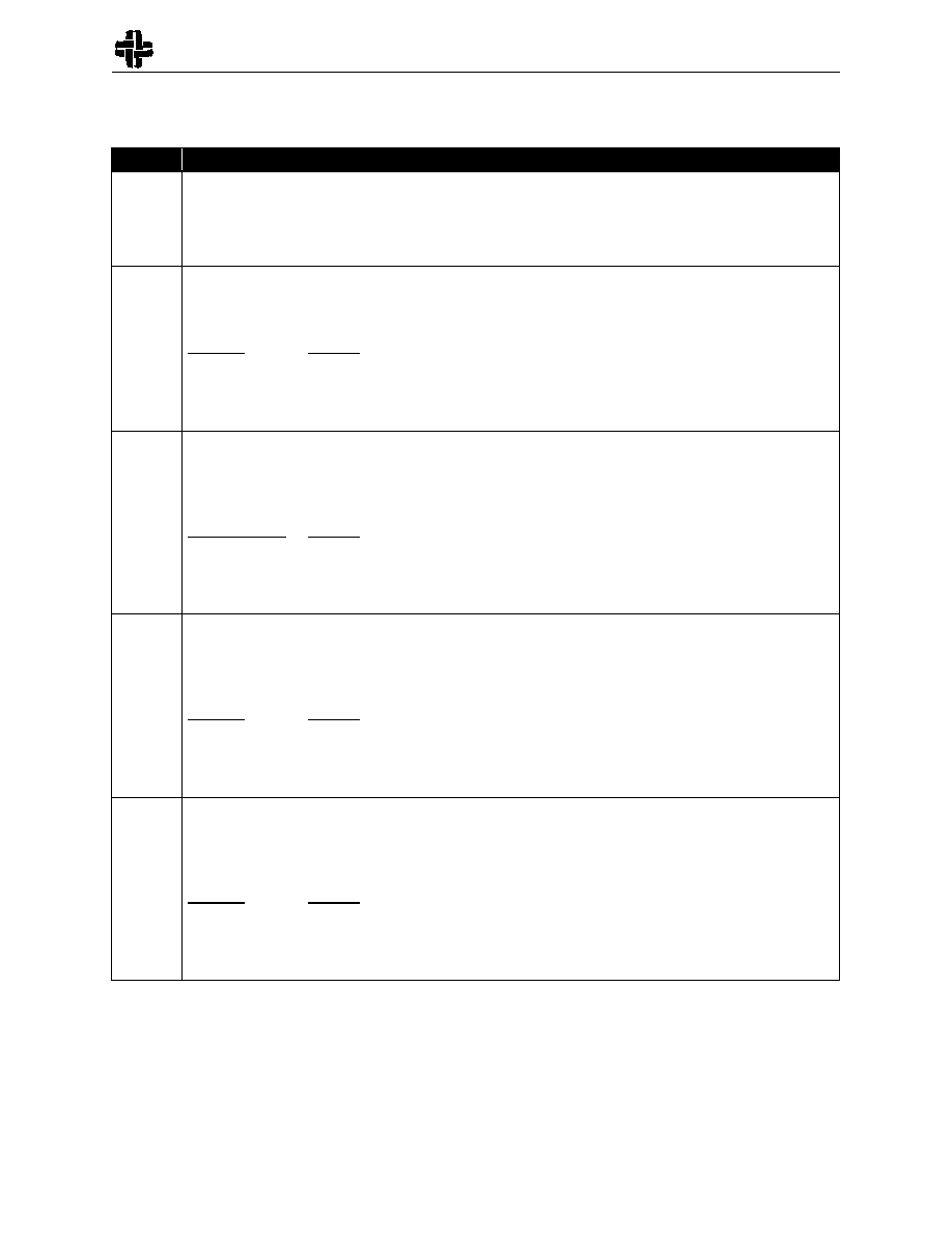
Table 6
IOB Programming Commands
Signal
Description
RCC[3]
Bus Repeater Enable. Setting this bit to a one enables the IOB to operate in Bus Repeater Mode, a special bi-
directional mode. When zero the IOB will not operate in Bus Repeater Mode.
When programming an IOB to use Bus Repeater Mode, all of the other control bits must be set to zeroes.
Attempting to combine other IOB options with Bus Repeater Mode may lead to unpredictable results.
RCC[2:1]
Input/Output Select. These two bits are used to configure the IOB as an input, output, input/output (bi-
directional mode), or no connect. When operating in bi-directional mode it is critical that the port be assigned
input and output enables so that it can be tri-stated appropriately to avoid contention.
RCC[2:1]
Function
00
No Connect
01
Input
10
Output
11
Input / Output for Bi-Directional Mode
RCC[0]
and
RCB[9]
Output Enable Select. These two bits are used to select from the two available active low global output enables.
The output will be allowed to drive when its assigned output enable is asserted. An output port will be tri-stated
when its assigned output enable is de-asserted. When both output enables are selected, the two available active
low output enable signals are AND’s together to form the port’s combined output enable signal.
RCC[0], RCB[9]
Function
00
No Output Enable Selected
01
Output Enable 1
10
Output Enable 2
11
Both Output Enables
RCB[8:7]
Input Enable Select. These bits are used to assign a port one of the two available global input enable signals.
An input port will drive into the crosspoint array when its assigned input enable is asserted. When both input
enables are selected, the two available input enable signals are OR’d together to form the port’s combined input
enable signal.
RCB[8:7]
Function
00
No Input Enable Selected
01
Input Enable 1
10
Input Enable 2
11
Both Input Enables
RCB[6:5]
Output Clock Source. These bits are used to select a clock source for a registered output port. Each IOB can
select from one of two global clock inputs, or can use Next Neighbor Clocking. Next Neighbor Clocking uses
the signal on the next higher numbered port as a clock source. If no clock source is assigned to an output port,
it will operate in flow-through mode.
RCB[6:5]
Function
00
No Output Clock Source Selected
01
Output Clock Source 1
10
Output Clock Source 2
11
Next Neighbor Output Clock Source
相关PDF资料 |
PDF描述 |
|---|---|
| M37641M8-XXXHP | 8-BIT, MROM, 24 MHz, MICROCONTROLLER, PQFP80 |
| MC68HC711N4VFS2 | 8-BIT, UVPROM, 2 MHz, MICROCONTROLLER, CQCC84 |
| MC68A01P1 | 8-BIT, MROM, 1.5 MHz, MICROCONTROLLER, PDIP40 |
| MC68HC711M2VFE3 | 8-BIT, UVPROM, 3 MHz, MICROCONTROLLER, CQFP80 |
| ML9041A-XXACVWA | 17 X 100 DOTS DOT MAT LCD DRVR AND DSPL CTLR, UUC189 |
相关代理商/技术参数 |
参数描述 |
|---|---|
| MSX4541 | 制造商:Cinch Connectors 功能描述: |
| MSX4542 | 制造商:Cinch Connectors 功能描述: |
| MSX-50 | 制造商:未知厂家 制造商全称:未知厂家 功能描述:Photovoltaic Modules |
| MSX532 | 制造商:FAIRCHILD 制造商全称:Fairchild Semiconductor 功能描述:532 Port Digital Crosspoint Switch with LVTTL I/O’s |
| MSX532 WAF | 制造商:Fairchild Semiconductor Corporation 功能描述: |
发布紧急采购,3分钟左右您将得到回复。