- 您现在的位置:买卖IC网 > PDF目录11671 > MXB7846EEE+ (Maxim Integrated Products)IC CNTRLR TOUCH RES 16QSOP PDF资料下载
参数资料
| 型号: | MXB7846EEE+ |
| 厂商: | Maxim Integrated Products |
| 文件页数: | 10/24页 |
| 文件大小: | 0K |
| 描述: | IC CNTRLR TOUCH RES 16QSOP |
| 其它有关文件: | Automotive Product Guide |
| 产品培训模块: | Lead (SnPb) Finish for COTS Obsolescence Mitigation Program |
| 标准包装: | 100 |
| 类型: | 温度传感器 |
| 输入类型: | 模拟 |
| 输出类型: | 数字 |
| 接口: | 4 线 |
| 电流 - 电源: | 950µA |
| 安装类型: | 表面贴装 |
| 封装/外壳: | 16-SSOP(0.154",3.90mm 宽) |
| 供应商设备封装: | 16-QSOP |
| 包装: | 管件 |
| 产品目录页面: | 1424 (CN2011-ZH PDF) |
MXB7846
2.375V to 5.25V, 4-Wire Touch-Screen Controller
with Internal Reference and Temperature Sensor
18
______________________________________________________________________________________
byte (see Tables 3 and 4). Once the processor instructs
the MXB7846 to initiate a conversion, the MXB7846
biases the touch screen through the internal switches at
the beginning of the acquisition period. The voltage
transient at the touch screen needs to settle down to a
stable voltage before the acquisition period is over.
After the acquisition period is over, the A/D converter
goes into a conversion period with all internal switches
turned off if the device is in single-ended mode. If the
device is in differential mode, the internal switches
remain on from the start of the acquisition period to the
end of the conversion period.
Power-On Reset
When power is first applied, internal power-on circuitry
resets the MXB7846. Allow 10s for the first conversion
after the power supplies stabilize. If
CS is low, the first
logic 1 on DIN is interpreted as a start bit. Until a con-
version takes place, DOUT shifts out zeros. On power-
up, allow time for the reference to stabilize.
Power Modes
Save power by placing the converter in one of two low-
current operating modes or in full power down between
conversions. Select the power-down mode through
PD1 and PD0 of the control byte (Tables 3 and 4).
The software power-down modes take effect after the
conversion is completed. The serial interface remains
active while waiting for a new control byte to start a con-
version and switches to full-power mode. After complet-
ing its conversion, the MXB7846 enters the programmed
power mode until a new control byte is received.
The power-up wait before conversion period is depen-
dent on the power-down state. When exiting software
low-power modes, conversion can start immediately
when running at decreased clock rates. Upon power-
on reset, the MXB7846 is in power-down mode with
PD1 = 0 and PD0 = 0. When exiting software shutdown,
the MXB7846 is ready to perform a conversion in 10s
with an external reference. When using the internal ref-
erence, allow enough time for reference to settle to 12-
bit accuracy when exiting full power-down mode, as
shown in the
Typical Operating Characteristics.
PD1 = 1, PD0 = 1
In this mode, the MXB7846 is always powered up and
both the reference and the ADC are always on. The
device remains fully powered after the current conver-
sion completes.
PD1 = 0, PD0 = 0
In this mode, the MXB7846 powers down after the cur-
rent conversion completes or on the next rising edge of
CS, whichever occurs first. The next control byte
received on DIN powers up the MXB7846. At the start
of a new conversion, it instantly powers up. When each
conversion is finished, the part enters power-down
mode, unless otherwise indicated. The first conversion
after the ADC returns to full power is valid for differen-
tial conversions and single-ended measurement con-
versions when using an external reference.
When operating at full speed and 16 clocks per conver-
sion, the difference in power consumption between
PD1 = 0, PD0 = 1, and PD1 = 0, PD0 = 0 is negligible.
Also, in the case where the conversion rate is
decreased by slowing the frequency of the DCLK input,
the power consumption between these two modes is
not very different. When the DCLK frequency is kept at
the maximum rate during a conversion, conversions are
done less often. There is a significant difference in
power consumption between these two modes.
PD1 = 1, PD0 = 0
In this mode, the MXB7846 is powered down. This
mode becomes active after the current conversion
completes or on the next rising edge of
CS, whichever
occurs first. The next command byte received on the
DIN returns the MXB7846 to full power. The first conver-
sion after the ADC returns to full power is valid.
PD1 = 0, PD0 = 1
This mode turns the internal reference off and leaves
the ADC on to perform conversions using an external
reference.
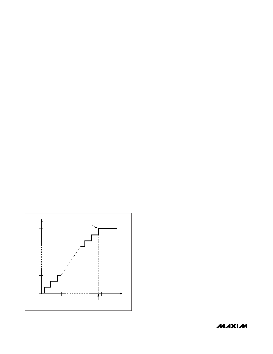
OUTPUT CODE
FS = (VREF+ - VREF-)
FS-3/2LSB
FULL-SCALE
TRANSITION
INPUT VOLTAGE (LSB) = [(V+IN) - (V-IN)]
12
3
FS
0
11…111
11…110
11…101
00…011
00…010
00…001
00…000
1LSB =
(VREF+ - VREF-)
4096
Figure 12. Ideal Input Voltages and Output Codes
相关PDF资料 |
PDF描述 |
|---|---|
| MAX6682MUA+ | IC THERMISTOR TO DGTL 8UMAX |
| VI-BTK-IW-F3 | CONVERTER MOD DC/DC 40V 100W |
| VI-BTJ-IX-F2 | CONVERTER MOD DC/DC 36V 75W |
| 2081202-1 | CONN PLUG SMA CRIMP RG402 |
| DS1876T+ | IC CTRLR SFP DUAL LDD 28TQFN |
相关代理商/技术参数 |
参数描述 |
|---|---|
| MXB7846EEE+ | 功能描述:触摸屏转换器和控制器 2.375-5.25V 4-Wire Touch-Screen Ctlr RoHS:否 制造商:Microchip Technology 类型:Resistive Touch Controllers 输入类型:3 Key 数据速率:140 SPS 分辨率:10 bit 接口类型:4-Wire, 5-Wire, 8-Wire, I2C, SPI 电源电压:2.5 V to 5.25 V 电源电流:17 mA 工作温度:- 40 C to + 85 C 封装 / 箱体:SSOP-20 |
| MXB7846EEE+T | 功能描述:触摸屏转换器和控制器 2.375-5.25V 4-Wire Touch-Screen Ctlr RoHS:否 制造商:Microchip Technology 类型:Resistive Touch Controllers 输入类型:3 Key 数据速率:140 SPS 分辨率:10 bit 接口类型:4-Wire, 5-Wire, 8-Wire, I2C, SPI 电源电压:2.5 V to 5.25 V 电源电流:17 mA 工作温度:- 40 C to + 85 C 封装 / 箱体:SSOP-20 |
| MXB7846EEE-T | 功能描述:触摸屏转换器和控制器 RoHS:否 制造商:Microchip Technology 类型:Resistive Touch Controllers 输入类型:3 Key 数据速率:140 SPS 分辨率:10 bit 接口类型:4-Wire, 5-Wire, 8-Wire, I2C, SPI 电源电压:2.5 V to 5.25 V 电源电流:17 mA 工作温度:- 40 C to + 85 C 封装 / 箱体:SSOP-20 |
| MXB7846EUE | 功能描述:触摸屏转换器和控制器 RoHS:否 制造商:Microchip Technology 类型:Resistive Touch Controllers 输入类型:3 Key 数据速率:140 SPS 分辨率:10 bit 接口类型:4-Wire, 5-Wire, 8-Wire, I2C, SPI 电源电压:2.5 V to 5.25 V 电源电流:17 mA 工作温度:- 40 C to + 85 C 封装 / 箱体:SSOP-20 |
| MXB7846EUE+ | 功能描述:触摸屏转换器和控制器 2.375-5.25V 4-Wire Touch-Screen Ctlr RoHS:否 制造商:Microchip Technology 类型:Resistive Touch Controllers 输入类型:3 Key 数据速率:140 SPS 分辨率:10 bit 接口类型:4-Wire, 5-Wire, 8-Wire, I2C, SPI 电源电压:2.5 V to 5.25 V 电源电流:17 mA 工作温度:- 40 C to + 85 C 封装 / 箱体:SSOP-20 |
发布紧急采购,3分钟左右您将得到回复。