- 您现在的位置:买卖IC网 > PDF目录19528 > NCP1201D100R2 (ON Semiconductor)IC CTRLR PWM CM OTP 8SOIC PDF资料下载
参数资料
| 型号: | NCP1201D100R2 |
| 厂商: | ON Semiconductor |
| 文件页数: | 16/19页 |
| 文件大小: | 0K |
| 描述: | IC CTRLR PWM CM OTP 8SOIC |
| 产品变化通告: | LTB Notification 03/Jan/2008 |
| 标准包装: | 2,500 |
| 输出隔离: | 隔离 |
| 频率范围: | 92kHz ~ 117kHz |
| 输入电压: | 12.5 V ~ 16 V |
| 输出电压: | 500V |
| 工作温度: | -40°C ~ 150°C |
| 封装/外壳: | 8-SOIC(0.154",3.90mm 宽) |
| 供应商设备封装: | 8-SOICN |
| 包装: | 带卷 (TR) |
�� �
�
�NCP1201�
�Protecting� the� Controller� Against� Negative�
�Spikes�
�As� with� any� controller� built� upon� a� CMOS� technology,� it�
�is� the� designer� ’s� duty� to� avoid� the� presence� of� negative�
�spikes� on� sensitive� pins.� Negative� signals� have� the� bad� habit�
�to� forward� bias� the� controller� substrate� and� induce� erratic�
�behaviors.� Sometimes,� the� injection� can� be� so� strong� that�
�internal� parasitic� SCRs� are� triggered,� engendering�
�irremediable� damages� to� the� IC� if� they� are� a� low� impedance�
�path� is� offered� between� V� CC� and� GND.� If� the� current� sense�
�pin� is� often� the� seat� of� such� spurious� signals,� the�
�high--voltage� pin� can� also� be� the� source� of� problems� in�
�certain� circumstances.� During� the� turn--off� sequence,� e.g.�
�fed� by� its� V� CC� capacitor� and� keeps� activating� the� MOSFET�
�ON� and� OFF� with� a� peak� current� limited� by� Rsense.�
�Unfortunately,� if� the� quality� coefficient� Q� of� the� resonating�
�network� formed� by� Lp� and� Cbulk� is� low� (e.g.� the� MOSFET�
�Rdson� +� Rsense� are� small),� conditions� are� met� to� make� the�
�circuit� resonate� and� thus� negatively� bias� the� controller.� Since�
�we� are� talking� about� ms� pulses,� the� amount� of� injected�
�charge� (Q� =� I� x� t)� immediately� latches� the� controller� which�
�brutally� discharges� its� V� CC� capacitor.� If� this� V� CC� capacitor�
�is� of� sufficient� value,� its� stored� energy� damages� the�
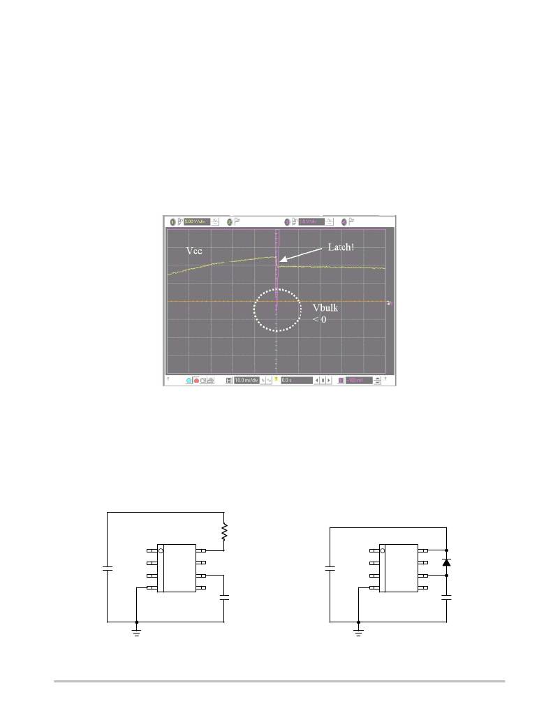
�controller.� Figure� 35� depicts� a� typical� negative� shot�
�occurring� on� the� HV� pin� where� the� brutal� V� CC� discharge�
�testifies� for� latchup.�
�when� the� user� unplugs� the� power� supply,� the� controller� is� still�
�Figure� 35.� A� negative� spike� takes� place� on� the� Bulk� capacitor� at� the� switch--off� sequence�
�Simple� and� inexpensive� cures� exist� to� prevent� from�
�internal� parasitic� SCR� activation.� One� of� them� consists� in�
�inserting� a� resistor� in� series� with� the� high--voltage� pin� to�
�keep� the� negative� current� to� the� lowest� when� the� bulk�
�becomes� negative� (Figure� 36).� Please� note� that� the� negative�
�spike� is� clamped� to� –2� x� Vf� due� to� the� diode� bridge.� Please�
�refer� to� AND8069� for� power� dissipation� calculations.�
�3�
�Rbulk�
�>� 4.7� k�
�2�
�Another� option� (Figure� 37)� consists� in� wiring� a� diode� from�
�V� CC� to� the� bulk� capacitor� to� force� V� CC� to� reach� UVLOlow�
�sooner� and� thus� stops� the� switching� activity� before� the� bulk�
�capacitor� gets� deeply� discharged.� For� security� reasons,� two�
�diodes� can� be� connected� in� series.�
�3�
�+�
�Cbulk�
�1�
�2�
�3�
�4�
�8�
�7�
�6�
�5�
�1� +�
�CV� CC�
�+�
�Cbulk�
�1�
�2�
�3�
�4�
�8�
�7�
�6�
�5�
�D3�
�1N4007�
�1� +�
�CV� CC�
�Figure� 36.� A� simple� resistor� in� series� avoids� any�
�latchup� in� the� controller�
�Figure� 37.� or� a� diode� forces� V� CC� to� reach�
�UVLOlow� sooner�
�http://onsemi.com�
�16�
�相关PDF资料 |
PDF描述 |
|---|---|
| ESA50DTBS | CONN EDGECARD 100PS R/A .125 SLD |
| EPM7064STI100-7N | IC MAX 7000 CPLD 64 100-TQFP |
| GBM10DTAT | CONN EDGECARD 20POS R/A .156 SLD |
| PR6002-T | DIODE FAST REC 6A 100V R-6 |
| NCP1014ST65T3 | IC OFFLINE SWIT SMPS CM SOT223 |
相关代理商/技术参数 |
参数描述 |
|---|---|
| NCP1201D100R2G | 功能描述:电流型 PWM 控制器 ANALOG POWER CONV RoHS:否 制造商:Texas Instruments 开关频率:27 KHz 上升时间: 下降时间: 工作电源电压:6 V to 15 V 工作电源电流:1.5 mA 输出端数量:1 最大工作温度:+ 105 C 安装风格:SMD/SMT 封装 / 箱体:TSSOP-14 |
| NCP1201D60R2 | 功能描述:电流型 PWM 控制器 Current Mode PWM RoHS:否 制造商:Texas Instruments 开关频率:27 KHz 上升时间: 下降时间: 工作电源电压:6 V to 15 V 工作电源电流:1.5 mA 输出端数量:1 最大工作温度:+ 105 C 安装风格:SMD/SMT 封装 / 箱体:TSSOP-14 |
| NCP1201D60R2G | 功能描述:电流型 PWM 控制器 Current Mode PWM w/Fault Protection RoHS:否 制造商:Texas Instruments 开关频率:27 KHz 上升时间: 下降时间: 工作电源电压:6 V to 15 V 工作电源电流:1.5 mA 输出端数量:1 最大工作温度:+ 105 C 安装风格:SMD/SMT 封装 / 箱体:TSSOP-14 |
| NCP1201P100 | 功能描述:电流型 PWM 控制器 Current Mode PWM RoHS:否 制造商:Texas Instruments 开关频率:27 KHz 上升时间: 下降时间: 工作电源电压:6 V to 15 V 工作电源电流:1.5 mA 输出端数量:1 最大工作温度:+ 105 C 安装风格:SMD/SMT 封装 / 箱体:TSSOP-14 |
| NCP1201P100G | 功能描述:电流型 PWM 控制器 Current Mode PWM w/Fault Protection RoHS:否 制造商:Texas Instruments 开关频率:27 KHz 上升时间: 下降时间: 工作电源电压:6 V to 15 V 工作电源电流:1.5 mA 输出端数量:1 最大工作温度:+ 105 C 安装风格:SMD/SMT 封装 / 箱体:TSSOP-14 |
发布紧急采购,3分钟左右您将得到回复。