- 您现在的位置:买卖IC网 > PDF目录20425 > NCP1203GEVB (ON Semiconductor)EVAL BOARD FOR NCP1203G PDF资料下载
参数资料
| 型号: | NCP1203GEVB |
| 厂商: | ON Semiconductor |
| 文件页数: | 10/16页 |
| 文件大小: | 0K |
| 描述: | EVAL BOARD FOR NCP1203G |
| 设计资源: | NCP1203GEVB BOM NCP1203GEVB Gerber Files NCP1203 EVB Schematic |
| 标准包装: | 1 |
| 主要目的: | AC/DC,主面 |
| 输出及类型: | 1,隔离 |
| 输出电压: | 19V |
| 电流 - 输出: | 4A |
| 输入电压: | 85 ~ 230VAC |
| 稳压器拓扑结构: | 回扫 |
| 频率 - 开关: | 60kHz |
| 板类型: | 完全填充 |
| 已供物品: | 板 |
| 已用 IC / 零件: | NPC1200 |
| 其它名称: | NCP1203GEVBOS |
�� �
�
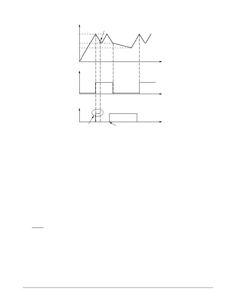
�NCP1200�
�V� CC�
�Regulation�
�Occurs� Here�
�11.4� V�
�Latchoff�
�9.8� V�
�Phase�
�6.3� V�
�Time�
�Drv�
�Internal�
�Driver�
�Pulses�
�Driver�
�Pulses�
�Time�
�Fault�
�Flag�
�Fault� is�
�Relaxed�
�Time�
�Startup� Phase�
�Fault� Occurs� Here�
�Figure� 20.� If� the� fault� is� relaxed� during� the� V� CC� natural� fall� down� sequence,� the� IC� automatically� resumes.�
�If� the� fault� persists� when� V� CC� reached� UVLO� L� ,� then� the� controller� cuts� everything� off� until� recovery.�
�D� t� +� D� V� @� C� ,� with� D� V� =� 2V.� Then� for� a� wanted� D� t� of� 10� ms,�
�Calculating� the� V� CC� Capacitor�
�As� the� above� section� describes,� the� fall� down� sequence�
�depends� upon� the� V� CC� level:� how� long� does� it� take� for� the�
�V� CC� line� to� go� from� 11.4� V� to� 9.8� V?� The� required� time�
�depends� on� the� startup� sequence� of� your� system,� i.e.� when�
�you� first� apply� the� power� to� the� IC.� The� corresponding�
�transient� fault� duration� due� to� the� output� capacitor� charging�
�must� be� less� than� the� time� needed� to� discharge� from� 11.4� V�
�to� 9.8� V,� otherwise� the� supply� will� not� properly� start.� The� test�
�consists� in� either� simulating� or� measuring� in� the� lab� how�
�much� time� the� system� takes� to� reach� the� regulation� at� full�
�load.� Let’s� suppose� that� this� time� corresponds� to� 6ms.�
�Therefore� a� V� CC� fall� time� of� 10� ms� could� be� well�
�appropriated� in� order� to� not� trigger� the� overload� detection�
�circuitry.� If� the� corresponding� IC� consumption,� including�
�the� MOSFET� drive,� establishes� at� 1.5� mA,� we� can� calculate�
�the� required� capacitor� using� the� following� formula:�
�i�
�C� equals� 8� m� F� or� 10� m� F� for� a� standard� value.� When� an�
�overload� condition� occurs,� the� IC� blocks� its� internal�
�circuitry� and� its� consumption� drops� to� 350� m� A� typical.� This�
�appends� at� V� CC� =� 9.8� V� and� it� remains� stuck� until� V� CC�
�reaches� 6.5� V:� we� are� in� latchoff� phase.� Again,� using� the�
�calculated� 10� m� F� and� 350� m� A� current� consumption,� this�
�latchoff� phase� lasts:� 109� ms.�
�Protecting� the� Controller� Against� Negative� Spikes�
�As� with� any� controller� built� upon� a� CMOS� technology,� it�
�is� the� designer� ’s� duty� to� avoid� the� presence� of� negative�
�spikes� on� sensitive� pins.� Negative� signals� have� the� bad� habit�
�to� forward� bias� the� controller� substrate� and� induce� erratic�
�behaviors.� Sometimes,� the� injection� can� be� so� strong� that�
�internal� parasitic� SCRs� are� triggered,� engendering�
�irremediable� damages� to� the� IC� if� they� are� a� low� impedance�
�path� is� offered� between� V� CC� and� GND.� If� the� current� sense�
�pin� is� often� the� seat� of� such� spurious� signals,� the�
�high� ?� voltage� pin� can� also� be� the� source� of� problems� in�
�certain� circumstances.� During� the� turn� ?� off� sequence,� e.g.�
�when� the� user� unplugs� the� power� supply,� the� controller� is� still�
�fed� by� its� V� CC� capacitor� and� keeps� activating� the� MOSFET�
�ON� and� OFF� with� a� peak� current� limited� by� Rsense.�
�Unfortunately,� if� the� quality� coefficient� Q� of� the� resonating�
�network� formed� by� Lp� and� Cbulk� is� low� (e.g.� the� MOSFET�
�Rdson� +� Rsense� are� small),� conditions� are� met� to� make� the�
�circuit� resonate� and� thus� negatively� bias� the� controller.� Since�
�we� are� talking� about� ms� pulses,� the� amount� of� injected�
�charge� (Q� =� I� x� t)� immediately� latches� the� controller� which�
�brutally� discharges� its� V� CC� capacitor.� If� this� V� CC� capacitor�
�is� of� sufficient� value,� its� stored� energy� damages� the�
�controller.� Figure� 21� depicts� a� typical� negative� shot�
�occurring� on� the� HV� pin� where� the� brutal� V� CC� discharge�
�testifies� for� latchup.�
�http://onsemi.com�
�10�
�相关PDF资料 |
PDF描述 |
|---|---|
| 17PY-Z444-99VS | MOTOR STEP UNI 42MM SQ 24V DL |
| T95Z336K016ESAL | CAP TANT 33UF 16V 10% 2910 |
| R0.25S8-1224 | CONV DC/DC 0.25W 12V IN 24V OUT |
| TC1303DM-DDBK2 | BOARD DEMO TC1303C DFN ADJ-OUT |
| GBC22DRTS-S13 | CONN EDGECARD 44POS .100 EXTEND |
相关代理商/技术参数 |
参数描述 |
|---|---|
| NCP1203P100 | 功能描述:电流型 PWM 控制器 100KHz Current Mode RoHS:否 制造商:Texas Instruments 开关频率:27 KHz 上升时间: 下降时间: 工作电源电压:6 V to 15 V 工作电源电流:1.5 mA 输出端数量:1 最大工作温度:+ 105 C 安装风格:SMD/SMT 封装 / 箱体:TSSOP-14 |
| NCP1203P100G | 功能描述:电流型 PWM 控制器 100KHz Current Mode SMPS PWM RoHS:否 制造商:Texas Instruments 开关频率:27 KHz 上升时间: 下降时间: 工作电源电压:6 V to 15 V 工作电源电流:1.5 mA 输出端数量:1 最大工作温度:+ 105 C 安装风格:SMD/SMT 封装 / 箱体:TSSOP-14 |
| NCP1203P40 | 功能描述:交流/直流开关转换器 40KHz Current Mode RoHS:否 制造商:STMicroelectronics 输出电压:800 V 输入/电源电压(最大值):23.5 V 输入/电源电压(最小值):11.5 V 开关频率:115 kHz 电源电流:1.6 mA 工作温度范围:- 40 C to + 150 C 安装风格:SMD/SMT 封装 / 箱体:SSO-10 封装:Reel |
| NCP1203P40G | 功能描述:电流型 PWM 控制器 40KHz Current Mode SMPS PWM RoHS:否 制造商:Texas Instruments 开关频率:27 KHz 上升时间: 下降时间: 工作电源电压:6 V to 15 V 工作电源电流:1.5 mA 输出端数量:1 最大工作温度:+ 105 C 安装风格:SMD/SMT 封装 / 箱体:TSSOP-14 |
| NCP1203P60 | 功能描述:电流型 PWM 控制器 60KHz Current Mode RoHS:否 制造商:Texas Instruments 开关频率:27 KHz 上升时间: 下降时间: 工作电源电压:6 V to 15 V 工作电源电流:1.5 mA 输出端数量:1 最大工作温度:+ 105 C 安装风格:SMD/SMT 封装 / 箱体:TSSOP-14 |
发布紧急采购,3分钟左右您将得到回复。