- 您现在的位置:买卖IC网 > PDF目录19698 > NCP1351CDR2G (ON Semiconductor)IC CTRLR PWM PROG CM OTP 8SOIC PDF资料下载
参数资料
| 型号: | NCP1351CDR2G |
| 厂商: | ON Semiconductor |
| 文件页数: | 20/27页 |
| 文件大小: | 0K |
| 描述: | IC CTRLR PWM PROG CM OTP 8SOIC |
| 标准包装: | 2,500 |
| 输出隔离: | 隔离 |
| 频率范围: | 调节 |
| 输入电压: | 9.5 V ~ 28 V |
| 工作温度: | -25°C ~ 125°C |
| 封装/外壳: | 8-SOIC(0.154",3.90mm 宽) |
| 供应商设备封装: | 8-SOICN |
| 包装: | 带卷 (TR) |
第1页第2页第3页第4页第5页第6页第7页第8页第9页第10页第11页第12页第13页第14页第15页第16页第17页第18页第19页当前第20页第21页第22页第23页第24页第25页第26页第27页
�� �
�
�NCP1351�
�Let� us� round� it� to� 0.25� or� 1/N� =� 4�
�From� Equation� 17,� a� K� factor� of� 0.8� (40%� ripple)� ensures� a�
�good� operation� over� universal� mains.� It� leads� to� an�
�inductance� of:�
�I� peak�
�L� +�
�(100�
�65� k�
�43)2�
�0.8� 72�
�+� 493� m� H�
�(eq.� 23)�
�I� 1�
�D� I� L�
�D� IL� +�
�Vin_mind max�
�LFSW�
�+�
�100�
�493� u�
�0.43�
�65� k�
�(eq.� 24)�
�+� 1.34� A� peak-to-peak�
�I� valley�
�The� peak� current� can� be� evaluated� to� be:�
�Iin_avg� +�
�Pout�
�h� Vin_min�
�+�
�19�
�0.8�
�3�
�100�
�+� 712� mA�
�(eq.� 25)�
�I� avg�
�Ipeak� +�
�Iavg�
�d�
�)�
�D� IL�
�2�
�+�
�0.712�
�0.43�
�)�
�1.34�
�2�
�+� 2.33� A�
�(eq.� 26)�
�t�
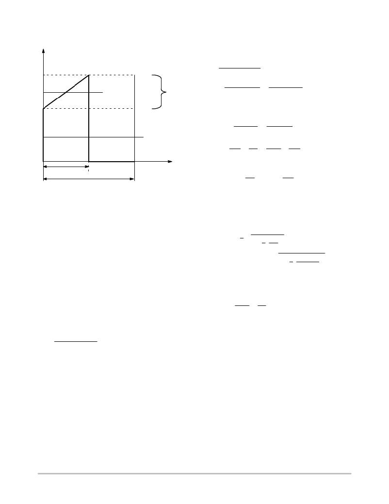
�On� Figure� 26,� I� 1� can� also� be� calculated:�
�DT� SW�
�T� SW�
�II� +� Ipeak� *�
�D� IL�
�2�
�+� 2.33� *�
�1.34�
�2�
�+� 1.65� A�
�(eq.� 27)�
�Figure� 26.� Primary� Inductance� Current� Evolution�
�The� valley� current� is� also� found� to� be:�
�in� CCM�
�Ivalley� +� Ipeak� *� D� IL� +� 2.33� *� 1.34� +� 1.0� A�
�(eq.� 28)�
�2.� Calculate� the� maximum� operating� duty-cycle� for�
�this� flyback� converter� operated� in� CCM:�
�4.� Based� on� the� above� numbers,� we� can� now� evaluate�
�the� RMS� current� circulating� in� the� MOSFET� and�
�the� sense� resistor:�
�d� max� +�
�Vout� N�
�Vout� N� )� Vin_min�
�+�
�19�
�19� 4�
�4� )� 100�
�+� 0.43�
�(eq.� 21)�
�Id_rms� +� II� d�
�1� )�
�1� D� IL� 2�
�3� 2I1�
�In� this� equation,� the� CCM� duty-cycle� does� not� exceed�
�50%.� The� design� should� thus� be� free� of� subharmonic�
�+� 1.65�
�0.65�
�1� )�
�1�
�3� 2�
�1.34�
�1.65�
�2�
�(eq.� 29)�
�oscillations� in� steady-state� conditions.� If� necessary,�
�negative� ramp� compensation� is� however� feasible� by� the�
�auxiliary� winding.�
�3.� To� obtain� the� primary� inductance,� we� can� use� the�
�+� 1.1� A�
�5.� The� current� peaks� to� 2.33� A.� Selecting� a� 1� V� drop�
�across� the� sense� resistor,� we� can� compute� its� value:�
�following� equation� which� expresses� the� inductance�
�in� relationship� to� a� coefficient� k.� This� coefficient�
�Rsense� +�
�1�
�Ipeak�
�+�
�1�
�2.5�
�+� 0.4� W�
�(eq.� 30)�
�L� +�
�actually� dictates� the� depth� of� the� CCM� operation.�
�If� it� goes� to� 2,� then� we� are� in� DCM.�
�(Vin_mind max)2�
�(eq.� 22)�
�FSWKPin�
�To� generate� 1� V,� the� offset� resistor� will� be� 3.7� k� W� ,� as� already�
�explained.� Using� Equation� 29,� the� power� dissipated� in� the�
�sense� element� reaches:�
�Psense� +� Rsense� Id_rms2� +� 0.4� 1.12� +� 484� mW�
�where� K� =� D� I� L� /I� I� and� defines� the� amount� of� ripple� we� want�
�in� CCM� (see� Figure� 26).�
�?� Small� K:� deep� CCM,� implying� a� large� primary�
�inductance,� a� low� bandwidth� and� a� large� leakage�
�inductance.�
�?� Large� K:� approaching� BCM� where� the� RMS� losses� are�
�the� worse,� but� smaller� inductance,� leading� to� a� better�
�leakage� inductance.�
�(eq.� 31)�
�6.� To� switch� at� 65� kHz,� the� C� t� capacitor� connected� to�
�pin� 2� will� be� selected� to� 180� pF.�
�7.� As� the� load� changes,� the� operating� frequency� will�
�automatically� adjust� to� satisfy� either� equation� 5�
�(high� power,� CCM)� or� equation� 6� in� lighter� load�
�conditions� (DCM).�
�Figure� 27� portrays� a� possible� application� schematic�
�implementing� what� we� discussed� in� the� above� lines.�
�http://onsemi.com�
�20�
�相关PDF资料 |
PDF描述 |
|---|---|
| ECC05DJBN-S1136 | CONN EDGECARD 10PS .100 PRESSFIT |
| V72A15E400BL3 | CONVERTER MOD DC/DC 15V 400W |
| MIC5201-3.0BMM TR | IC REG LDO 3V .2A 8-MSOP |
| 171-037-213R031 | CONN DB37 FEMALE DIP SLD NICKEL |
| SG5841SZ | IC PWM FLYBACK ISOLATED CM 8-SOP |
相关代理商/技术参数 |
参数描述 |
|---|---|
| NCP1351CPG | 功能描述:电流型 PWM 控制器 VRIABLE OFF TM CNTRL RoHS:否 制造商:Texas Instruments 开关频率:27 KHz 上升时间: 下降时间: 工作电源电压:6 V to 15 V 工作电源电流:1.5 mA 输出端数量:1 最大工作温度:+ 105 C 安装风格:SMD/SMT 封装 / 箱体:TSSOP-14 |
| NCP1351DDR2G | 功能描述:电流型 PWM 控制器 PWM CONTROLLER RoHS:否 制造商:Texas Instruments 开关频率:27 KHz 上升时间: 下降时间: 工作电源电压:6 V to 15 V 工作电源电流:1.5 mA 输出端数量:1 最大工作温度:+ 105 C 安装风格:SMD/SMT 封装 / 箱体:TSSOP-14 |
| NCP1351DPG | 功能描述:电流型 PWM 控制器 VRIABLE OFF TM CNTRL RoHS:否 制造商:Texas Instruments 开关频率:27 KHz 上升时间: 下降时间: 工作电源电压:6 V to 15 V 工作电源电流:1.5 mA 输出端数量:1 最大工作温度:+ 105 C 安装风格:SMD/SMT 封装 / 箱体:TSSOP-14 |
| NCP1351LEDGEVB | 功能描述:电源管理IC开发工具 20 W CONSTANT CUR LED DRV RoHS:否 制造商:Maxim Integrated 产品:Evaluation Kits 类型:Battery Management 工具用于评估:MAX17710GB 输入电压: 输出电压:1.8 V |
| NCP1351PRINTGEVB | 功能描述:电源管理IC开发工具 NCP1351 40 W PRINTER EVB RoHS:否 制造商:Maxim Integrated 产品:Evaluation Kits 类型:Battery Management 工具用于评估:MAX17710GB 输入电压: 输出电压:1.8 V |
发布紧急采购,3分钟左右您将得到回复。