- 您现在的位置:买卖IC网 > Datasheet目录996 > NCP1351LEDGEVB (ON Semiconductor)EVAL BOARD FOR NCP1351LEDG Datasheet资料下载
参数资料
| 型号: | NCP1351LEDGEVB |
| 厂商: | ON Semiconductor |
| 文件页数: | 16/27页 |
| 文件大小: | 0K |
| 描述: | EVAL BOARD FOR NCP1351LEDG |
| 设计资源: | NCP1351 EVB BOM NCP1351LEDGEVB Gerber Files NCP1351LED EVB Schematic |
| 标准包装: | 1 |
| 电流 - 输出 / 通道: | 700mA |
| 输出及类型: | 1,隔离 |
| 输出电压: | 33V |
| 特点: | 短路保护 |
| 输入电压: | 85 ~ 265 V |
| 已供物品: | 板 |
| 已用 IC / 零件: | NCP1351 |
| 其它名称: | NCP1351LEDGEVBOS |
第1页第2页第3页第4页第5页第6页第7页第8页第9页第10页第11页第12页第13页第14页第15页当前第16页第17页第18页第19页第20页第21页第22页第23页第24页第25页第26页第27页
�� �
�
�NCP1351�
�V� CC�
�I� timer�
�10� m�
�V� CC�
�D� aux�
�Timer�
�C� timer�
�100nF�
�V� CC�
�+�
�V� timer�
�5�
�+�
�-�
�S�
�Q�
�Q�
�20� m� s�
�Filter�
�CV� CC�
�I� CC�
�to� DRV�
�+�
�L� aux�
�Stage�
�P� on�
�R�
�FB�
�Reset�
�I� FB�
�I� FB�
�+�
�-�
�+�
�C1�
�100n�
�R1�
�2.5k�
�D� FB�
�I� FB�
�I� FB� <� 40� m� A� ?� =� Low�
�Else� =� High�
�V� CC� ==�
�VCC� (min)�
�?� Reset�
�DRV� Pulses�
�Auto-Recovery� -� B� Version�
�V� CC�
�C� timer�
�100nF�
�Timer�
�I� timer�
�10� m�
�+�
�V� timer�
�+�
�-�
�20� m� s�
�Filter�
�6V�
�V� CC�
�CV� CC�
�I� CC�
�+�
�D� aux�
�L� aux�
�V� CC�
�P� on�
�5�
�FB�
�Reset�
�I� FB�
�I� FB�
�+�
�-�
�+�
�SCR� Delatches� When�
�I� SCR� <� ICC� latch� (Few� m� A)�
�C1�
�100n�
�R1�
�2.5k�
�D� FB�
�I� FB�
�I� FB� <� 40� m� A� ?� =� Low�
�Else� =� High�
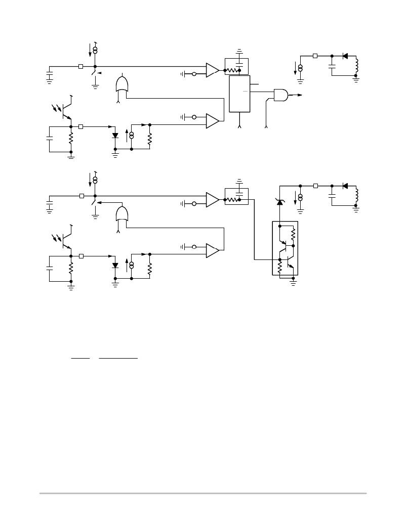
�Latched� -� A� Version�
�Figure� 19.� The� Internal� Fault� Management� Differs� Depending� on� the� Considered� Version�
�Knowing� both� the� ending� voltage� and� the� charge� current,�
�we� can� easily� calculate� the� timer� capacitor� value� for� a� given�
�delay.� Suppose� we� need� 40� ms.� In� that� case,� the� capacitor� is�
�simply:�
�designer� select� a� 100� kHz� maximum� switching� frequency,�
�then� the� error� flag� would� raise� and� start� the� timer� for� an�
�operating� frequency� above� ≈� 50� kHz.� Below� 50� kHz,� the�
�timer� pin� remains� grounded.� If� we� consider� a� DCM�
�Ctimer� +� timer� +�
�I T�
�Vtimer�
�11.7� m�
�5�
�40� m�
�+� 94� nF�
�(eq.� 16)�
�operation� at� full� load,� as� the� inductor� peak� current� is� kept�
�constant,� these� 50� kHz� correspond� to� 50%� of� the� maximum�
�delivered� power.� If� the� load� stays� between� 50%� and� 100%� of�
�Select� a� 100� nF� value.�
�To� let� the� designer� understand� the� behavior� behind� the�
�four� different� options� (A,� B,� C� and� D),� we� have� graphed�
�important� signals� during� a� fault� condition.� In� versions� A� and�
�B,� an� internal� error� flag� is� raised� as� soon� the� controller� hits�
�the� maximum� operating� frequency.� At� this� moment,� the�
�external� timer� capacitor� charge� begins.� If� the� fault� persists,�
�the� timer� capacitor� hits� the� fault� level� and� the� circuit� is� either�
�latched� (A)� or� enters� auto-recovery� burst� mode� (B).� If� the�
�fault� disappears,� the� timer� capacitor� is� simply� reset� to� 0� V� by�
�an� internal� switch.�
�On� version� C� and� D,� the� error� flag� is� asserted� as� soon� as�
�the� current� feedback� imposes� a� switching� frequency� roughly�
�its� nominal� value,� the� timer� continues� to� charge� until� it�
�reaches� the� final� level.� In� that� case,� the� circuit� latches� off� (C)�
�or� enters� auto-recovery� (D).� This� behavior� is� particularly�
�well� suited� for� applications� where� the� converter� delivers� a�
�moderate� average� power� but� is� subjected� to� sudden� peak�
�loading� conditions.� For� instance,� a� power� supply� is� designed�
�to� permanently� deliver� 20� W� but� is� sized� to� deliver� 80� W� in�
�peak� conditions.� During� these� 80� W� power� excursions,� the�
�timer� will� react� but� will� not� shut� down� the� power� supply.� On�
�the� contrary,� if� a� short-circuit� appends� or� if� the� transient�
�overload� lasts� too� long,� the� timer� will� immediately� start� to�
�further� shutdown� the� controller� in� order� to� protect� both� the�
�application� and� downstream� load.�
�equal� to� half� of� the� maximum� limit.� For� instance,� should� the�
�http://onsemi.com�
�16�
�相关PDF资料 |
PDF描述 |
|---|---|
| NCP3065BBGEVB | BOARD EVAL NCP3065 MR16 BOOST |
| NCP3066SCBCKGEVB | EVAL BOARD FOR NCP3066SCBCKG |
| NCP5005GEVB | EVAL BOARD FOR NCP5005G |
| NCP5006EVB | EVAL BOARD FOR NCP5006 |
| NCP5030MTTXGEVB | EVAL BOARD FOR NCP5030MTTXG |
相关代理商/技术参数 |
参数描述 |
|---|---|
| NCP1351PRINTGEVB | 功能描述:电源管理IC开发工具 NCP1351 40 W PRINTER EVB RoHS:否 制造商:Maxim Integrated 产品:Evaluation Kits 类型:Battery Management 工具用于评估:MAX17710GB 输入电压: 输出电压:1.8 V |
| NCP1377 | 制造商:ONSEMI 制造商全称:ON Semiconductor 功能描述:PWM Current-Mode Controller for Free-Running Quasi-Resonant Operation |
| NCP1377/D | 制造商:未知厂家 制造商全称:未知厂家 功能描述:PWM Current -Mode Controller |
| NCP1377_06 | 制造商:ONSEMI 制造商全称:ON Semiconductor 功能描述:PWM Current−Mode Controller for Free−Running Quasi−Resonant Operation |
| NCP1377_11 | 制造商:ONSEMI 制造商全称:ON Semiconductor 功能描述:PWM Current-Mode Controller for Free-Running Quasi-Resonant Operation |
发布紧急采购,3分钟左右您将得到回复。