- 您现在的位置:买卖IC网 > PDF目录13696 > NCP1547MNR2G (ON Semiconductor)IC REG BUCK ADJ 1.5A 18DFN PDF资料下载
参数资料
| 型号: | NCP1547MNR2G |
| 厂商: | ON Semiconductor |
| 文件页数: | 10/15页 |
| 文件大小: | 0K |
| 描述: | IC REG BUCK ADJ 1.5A 18DFN |
| 标准包装: | 1 |
| 类型: | 降压(降压) |
| 输出类型: | 可调式 |
| 输出数: | 1 |
| 输出电压: | 1.5 V ~ 24 V |
| 输入电压: | 4.5 V ~ 40 V |
| PWM 型: | 混合物 |
| 频率 - 开关: | 340kHz |
| 电流 - 输出: | 1.5A |
| 同步整流器: | 无 |
| 工作温度: | 0°C ~ 70°C |
| 安装类型: | 表面贴装 |
| 封装/外壳: | 18-VFDFN 裸露焊盘 |
| 包装: | 剪切带 (CT) |
| 供应商设备封装: | 18-DFN(5x6) |
| 其它名称: | NCP1547MNR2GOSCT |
�� �
�
�NCP1547�
�(VIN� *� VO� )� O� )�
�WDRV� +� 12� mA�
�V 2�
�VIN�
�where:�
�IRMS� +� IO� D(1� *� D)�
�The� base� current� of� a� bipolar� transistor� is� equal� to� collector�
�current� divided� by� beta� of� the� device.� Beta� of� 60� is� used� here�
�to� estimate� the� base� current.� The� Boost� pin� provides� the� base�
�current� when� the� transistor� needs� to� be� on.� The� power�
�dissipated� by� the� IC� due� to� this� current� is�
�D� =� switching� duty� cycle� which� is� equal� to� V� O� /V� IN� .�
�I� O� =� load� current.�
�WBASE� +� O�
�V 2�
�VIN�
�IS�
�60�
�where:�
�I� S� =� DC� switching� current.�
�When� the� power� switch� turns� on,� the� saturation� voltage�
�and� conduction� current� contribute� to� the� power� loss� of� a�
�non� ?� ideal� switch.� The� power� loss� can� be� quantified� as�
�WSAT� +�
�VO�
�VIN�
�IS�
�VSAT�
�where:�
�V� SAT� =� saturation� voltage� of� the� power� switch� which� is�
�shown� in� Figure� 7.�
�The� switching� loss� occurs� when� the� switch� experiences�
�both� high� current� and� voltage� during� each� switch� transition.�
�This� regulator� has� a� 30� ns� turn� ?� off� time� and� associated�
�power� loss� is� equal� to�
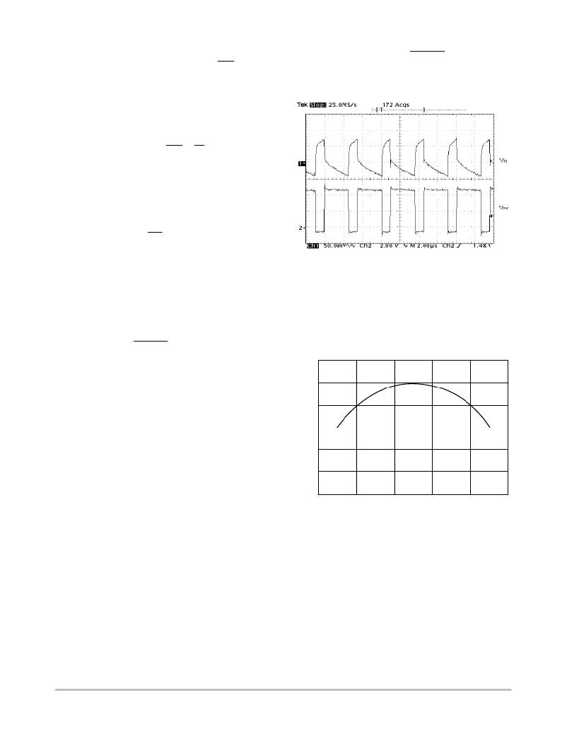
�Figure� 13.� Input� Voltage� Ripple� in� a� Buck� Converter�
�To� calculate� the� RMS� current,� multiply� the� load� current�
�with� the� constant� given� by� Figure� 14� at� each� duty� cycle.� It� is�
�a� common� practice� to� select� the� input� capacitor� with� an� RMS�
�current� rating� more� than� half� the� maximum� load� current.� If�
�multiple� capacitors� are� paralleled,� the� RMS� current� for� each�
�WS� +� S�
�I�
�2�
�VIN�
�30� ns�
�fS�
�capacitor� should� be� the� total� current� divided� by� the� number�
�of� capacitors.�
�The� turn� ?� on� time� is� much� shorter� and� thus� turn� ?� on� loss� is�
�not� considered� here.�
�The� total� power� dissipated� by� the� IC� is� sum� of� all� the� above�
�WIC� +� WQ� )� WDRV� )� WBASE� )� WSAT� )� WS�
�The� IC� junction� temperature� can� be� calculated� from� the�
�ambient� temperature,� IC� power� dissipation� and� thermal�
�resistance� of� the� package.� The� equation� is� shown� as� follows,�
�0.6�
�0.5�
�0.4�
�0.3�
�TJ� +� WIC�
�R� q� JA� )� TA�
�0.2�
�Minimum� Load� Requirement�
�0�
�0.2�
�0.4�
�0.6�
�0.8�
�1.0�
�As� pointed� out� in� the� previous� section,� a� minimum� load� is�
�required� for� this� regulator� due� to� the� pre� ?� driver� current�
�feeding� the� output.� Placing� a� resistor� equal� to� V� O� divided� by�
�12� mA� should� prevent� any� voltage� overshoot� at� light� load�
�conditions.� Alternatively,� the� feedback� resistors� can� be�
�valued� properly� to� consume� 12� mA� current.�
�COMPONENT� SELECTION�
�Input� Capacitor�
�In� a� buck� converter,� the� input� capacitor� witnesses� pulsed�
�current� with� an� amplitude� equal� to� the� load� current.� This�
�pulsed� current� and� the� ESR� of� the� input� capacitors� determine�
�the� V� IN� ripple� voltage,� which� is� shown� in� Figure� 13.� For� V� IN�
�ripple,� low� ESR� is� a� critical� requirement� for� the� input�
�capacitor� selection.� The� pulsed� input� current� possesses� a�
�significant� AC� component,� which� is� absorbed� by� the� input�
�capacitors.� The� RMS� current� of� the� input� capacitor� can� be�
�calculated� using:�
�0.1�
�0�
�DUTY� CYCLE�
�Figure� 14.� Input� Capacitor� RMS� Current� can� be�
�Calculated� by� Multiplying� Y� Value� with� Maximum� Load�
�Current� at� any� Duty� Cycle�
�Selecting� the� capacitor� type� is� determined� by� each�
�design’s� constraint� and� emphasis.� The� aluminum�
�electrolytic� capacitors� are� widely� available� at� lowest� cost.�
�Their� ESR� and� ESL� (equivalent� series� inductor)� are�
�relatively� high.� Multiple� capacitors� are� usually� paralleled� to�
�achieve� lower� ESR.� In� addition,� electrolytic� capacitors�
�usually� need� to� be� paralleled� with� a� ceramic� capacitor� for�
�filtering� high� frequency� noises.� The� OS� ?� CON� are� solid�
�aluminum� electrolytic� capacitors,� and� therefore� has� a� much�
�lower� ESR.� Recently,� the� price� of� the� OS� ?� CON� capacitors�
�has� dropped� significantly� so� that� it� is� now� feasible� to� use�
�http://onsemi.com�
�10�
�相关PDF资料 |
PDF描述 |
|---|---|
| SCX114-500 | INDUCTOR 50/202.07UH 0.70/0.35A |
| VI-J61-CZ-S | CONVERTER MOD DC/DC 12V 25W |
| ESC20DRYN-S93 | CONN EDGECARD 40POS DIP .100 SLD |
| MAX6727AKASDD5+T | IC SUPERVISOR MPU SOT23-8 |
| MAX6727AKASFD2+T | IC SUPERVISOR MPU SOT23-8 |
相关代理商/技术参数 |
参数描述 |
|---|---|
| NCP1550SN18T1 | 功能描述:直流/直流开关转换器 1.8V 2A Buck PWM/PFM RoHS:否 制造商:STMicroelectronics 最大输入电压:4.5 V 开关频率:1.5 MHz 输出电压:4.6 V 输出电流:250 mA 输出端数量:2 最大工作温度:+ 85 C 安装风格:SMD/SMT |
| NCP1550SN18T1G | 功能描述:直流/直流开关转换器 1.8V 2A Buck PWM/PFM w/Enable Soft Start RoHS:否 制造商:STMicroelectronics 最大输入电压:4.5 V 开关频率:1.5 MHz 输出电压:4.6 V 输出电流:250 mA 输出端数量:2 最大工作温度:+ 85 C 安装风格:SMD/SMT |
| NCP1550SN19T1 | 功能描述:直流/直流开关转换器 1.8V 2A Buck PWM/PFM RoHS:否 制造商:STMicroelectronics 最大输入电压:4.5 V 开关频率:1.5 MHz 输出电压:4.6 V 输出电流:250 mA 输出端数量:2 最大工作温度:+ 85 C 安装风格:SMD/SMT |
| NCP1550SN19T1G | 功能描述:直流/直流开关转换器 1.8V 2A Buck PWM/PFM w/Enable Soft Start RoHS:否 制造商:STMicroelectronics 最大输入电压:4.5 V 开关频率:1.5 MHz 输出电压:4.6 V 输出电流:250 mA 输出端数量:2 最大工作温度:+ 85 C 安装风格:SMD/SMT |
| NCP1550SN25T1 | 功能描述:直流/直流开关转换器 1.8V 2A Buck PWM/PFM RoHS:否 制造商:STMicroelectronics 最大输入电压:4.5 V 开关频率:1.5 MHz 输出电压:4.6 V 输出电流:250 mA 输出端数量:2 最大工作温度:+ 85 C 安装风格:SMD/SMT |
发布紧急采购,3分钟左右您将得到回复。