- 您现在的位置:买卖IC网 > PDF目录268194 > NE57607GDH-T (NXP SEMICONDUCTORS) 2-CHANNEL POWER SUPPLY SUPPORT CKT, PDSO8 PDF资料下载
参数资料
| 型号: | NE57607GDH-T |
| 厂商: | NXP SEMICONDUCTORS |
| 元件分类: | 电源管理 |
| 英文描述: | 2-CHANNEL POWER SUPPLY SUPPORT CKT, PDSO8 |
| 封装: | 4.40 MM, PLASTIC, SOT-530-1, VSOP-8 |
| 文件页数: | 9/10页 |
| 文件大小: | 131K |
| 代理商: | NE57607GDH-T |
Philips Semiconductors
Product data
NE57607
Two-cell Lithium-ion battery protection with
overcurrent, over- and under-voltage protection
2001 Oct 03
8
The R-C filters around the NE57607
One needs to place R-C filters on the positive input pins of the
NE57607. These are primarily to shield the IC from electrostatic
occurrences and spikes on the terminals of the battery pack. A
secondary need is during the occurrence of a short-circuit across
the battery pack terminals. Here, the Li-ion cell voltage could
collapse and cause the IC to enter an unpowered state. The R-Cs
then provide power during the first instance of the short circuit and
allow the IC to turn OFF the discharge MOSFET. The IC can then
enter an unpowered state. Lastly, the R-C filter on the node between
the two cells filters any noise voltage caused by noisy load current.
The values shown in Figure 6 are good for these purposes.
Selecting the Optimum MOSFETs:
For a 2-cell battery pack, a logic-level MOSFET should be used.
These MOSFETs have turn-on thresholds of 0.9 V and are
considered full-on at 4.5 V VGS. The total pack voltage will be a
maximum of 8.6 V which is within safe operating range of the gate
voltage which is typically more than two times the full-on voltage.
The MOSFETs should have a voltage rating greater than 20 V and
should have a high avalanche rating to survive any spikes
generated across the battery pack terminals.
The current rating of the MOSFETs should be greater than four
times the maximum “C-rating” of the cells. The current rating,
though, is more defined by the total series resistance of the battery
pack. The total resistance of the battery pack is given by Equation 1.
Rbat(tot) = 2(RDS(ON)) + 2Rcell
(Equation 1)
The total pack resistance is typically determined by the system
requirements. The total pack resistance directly determines how
much voltage droop will occur during pulses in load current.
Another consideration is the forward-biased safe operating area of
the MOSFET. During a short-circuit, the discharge current can easily
reach 10–15 times the “C-rating” of the cells. The MOSFET must
survive this current prior to the discharge MOSFET can be turned
OFF. So having an FBSOA envelope that exceeds 20 amperes for
5 ms would be safe.
The Charge MOSFET Circuit.
The NE57607 uses an isolated charge MOSFET drive arrangement.
This is to help keep ESD charges from entering the IC. The charge
MOSFET is normally ON until turned off by the IC. The CF pin uses
a current source to drive an external NPN transistor to turn OFF the
charge FET. If a charge has poor “compliance” or the no load voltage
of the charge can rise significantly above the rating of the battery
pack. This condition causes the source of the charge FET to go very
negative compared to the cell GND voltage after the charge FET
opens. This design allows the charge FET gate drive to “float” down
to this very negative voltage without upsetting the operation of the IC.
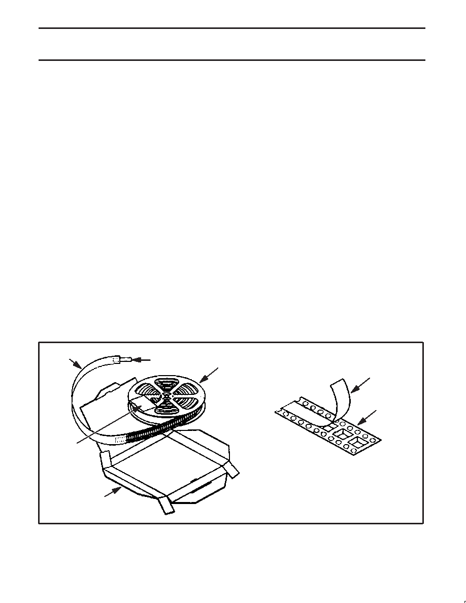
PACKING METHOD
SL01305
TAPE DETAIL
COVER TAPE
CARRIER TAPE
REEL
ASSEMBLY
TAPE
GUARD
BAND
BARCODE
LABEL
BOX
Figure 7. Tape and reel packing method.
相关PDF资料 |
PDF描述 |
|---|---|
| NJU7707F26A1 | POWER SUPPLY SUPPORT CKT, PDSO5 |
| NSR368-79I | 1-OUTPUT DC-DC REG PWR SUPPLY MODULE |
| NSR368-79LIPC | 1-OUTPUT DC-DC REG PWR SUPPLY MODULE |
| NFC40-24S12-M4E | 1-OUTPUT 40 W DC-DC REG PWR SUPPLY MODULE |
| NFC40-24S05-MX | 1-OUTPUT 40 W DC-DC REG PWR SUPPLY MODULE |
相关代理商/技术参数 |
参数描述 |
|---|---|
| NE57607H | 制造商:PHILIPS 制造商全称:NXP Semiconductors 功能描述:Two-cell Lithium-ion battery protection with overcurrent, over- and under-voltage protection |
| NE57607HDH | 制造商:PHILIPS 制造商全称:NXP Semiconductors 功能描述:Two-cell Lithium-ion battery protection with overcurrent, over- and under-voltage protection |
| NE57607K | 制造商:PHILIPS 制造商全称:NXP Semiconductors 功能描述:Two-cell Lithium-ion battery protection with overcurrent, over- and under-voltage protection |
| NE57607KDH | 制造商:PHILIPS 制造商全称:NXP Semiconductors 功能描述:Two-cell Lithium-ion battery protection with overcurrent, over- and under-voltage protection |
| NE57607XDH | 制造商:PHILIPS 制造商全称:NXP Semiconductors 功能描述:Two-cell Lithium-ion battery protection with overcurrent, over- and under-voltage protection |
发布紧急采购,3分钟左右您将得到回复。