参数资料
| 型号: | NP1100SBMCT3G |
| 厂商: | ON Semiconductor |
| 文件页数: | 5/7页 |
| 文件大小: | 0K |
| 描述: | IC TSPD SURGE DEVICE 80A SMB |
| 产品变化通告: | Product Discontinuation 19/Jul/2012 |
| 标准包装: | 2,500 |
| 电压 - 击穿: | 130V |
| 电压 - 断路: | 90V |
| 电压 - 导通状态: | 4V |
| 电流 - 峰值脉冲(8 x 20µs): | 250A |
| 电流 - 峰值脉冲(10 x 1000µs): | 80A |
| 电流 - 保持 (Ih): | 150mA |
| 元件数: | 1 |
| 电容: | 29pF |
| 封装/外壳: | DO-214AA,SMB |
| 包装: | 带卷 (TR) |
�� �
�
�NPMC� Series�
�Detailed� Operating� Description�
�The� TSPD� or� Thyristor� Surge� Protection� Device� are�
�specialized� silicon� based� overvoltage� protectors,� used� to�
�protect� sensitive� electronic� circuits� from� damaging�
�overvoltage� transient� surges� caused� by� induced� lightning�
�and� powercross� conditions.�
�The� TSPD� protects� by� switching� to� a� low� on� state� voltage�
�when� the� specified� protection� voltage� is� exceeded.� This� is�
�known� as� a� “crowbar”� effect.� When� an� overvoltage� occurs,�
�the� crowbar� device� changes� from� a� high� ?� impedance� to� a�
�low� ?� impedance� state.� This� low� ?� impedance� state� then� offers�
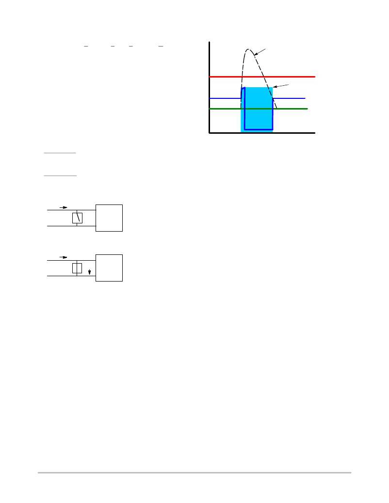
�Transient� Surge�
�Equipment� Failure� Threshold�
�TSPD� Protection� Voltage�
�Upper� Limit�
�Normal� System�
�Operating� Voltage�
�a� path� to� ground,� shunting� unwanted� surges� away� from� the�
�sensitive� circuits.�
�TSPD� Transparent�
�(open)�
�TSPD� Protection�
�(short)�
�TSPD� Transparent�
�(open)�
�This� crowbar� action� defines� the� TSPD’s� two� states� of�
�functionality:� Open� Circuit� and� Short� Circuit.�
�Open Circuit� –� The� TSPD� must� remain� transparent� during�
�normal� circuit� operation.� The� device� looks� like� an� open�
�across� the� two� wire� line.�
�Short Circuit� –� When� a� transient� surge� fault� exceeds� the�
�TSPD� protection� voltage� threshold,� the� devices� switches� on,�
�and� shorts� the� transient� to� ground,� safely� protecting� the�
�circuit.�
�Time�
�Figure� 6.� Protection� During� a� Transient� Surge�
�TSPD’s� are� useful� in� helping� designers� meet� safety� and�
�regulatory� standards� in� Telecom� equipment� including�
�GR� ?� 1089� ?� CORE,� ITU� ?� K.20,� ITU� ?� K.21,� ITU� ?� K.45,� FCC�
�Part� 68,� UL1950,� and� EN� 60950.�
�ON� Semiconductor� offers� a� full� range� of� these� products� in�
�the� NP� series� product� line.�
�I� (OP)�
�V� (OP)� TSPD�
�+� +�
�Protected�
�Equipment�
�?� ?�
�Normal� Circuit� Operation�
�?� TSPD� looks� like� an� open�
�?� Circuit� operates� normally�
�DEVICE� SELECTION�
�When� selecting� a� TSPD� use� the� following� key� selection�
�parameters.�
�Off� ?� State� Voltage� V� DRM�
�Choose� a� TSPD� that� has� an� Off� ?� State� Voltage� greater� than�
�the� normal� system� operating� voltage.� The� protector� should�
�I�
�+� (Fault)�
�+�
�I� (Fault)� Protected�
�V� (Fault)� TSPD�
�Operation� during� a� Fault�
�?� Fault� voltage� greater� than� V� bo� occurs�
�?� TSPD� shorts� fault� to� ground�
�?� After� short� duration� events� the� O/V�
�switches� back� to� an� open� condition�
�Equipment� ?� Worst� case� (Fail/Safe)�
�?� ?� ?� O/V� permanent� short�
�?� Equipment� protected�
�Figure� 5.� Normal� and� Fault� Conditions�
�The� electrical� characteristics� of� the� TSPD� help� the� user� to�
�define� the� protection� threshold� for� the� circuit.� During� the�
�open� circuit� condition� the� device� must� remain� transparent;�
�this� is� defined� by� the� I� DRM� .� The� I� DRM� should� be� as� low� as�
�possible.� The� typical� value� is� less� than� 5� m� A.�
�The� circuit� operating� voltage� and� protection� voltage� must�
�be� understood� and� considered� during� circuit� design.� The�
�V� (BO)� is� the� guaranteed� maximum� voltage� that� the� protected�
�circuit� will� see,� this� is� also� known� as� the� protection� voltage.�
�The� V� DRM� is� the� guaranteed� maximum� voltage� that� will�
�keep� the� TSPD� in� its� normal� open� circuit� state.� The� TSPD�
�V� (BO)� is� typically� a� 20� ?� 30%� higher� than� the� V� DRM� .� Based�
�on� these� characteristics� it� is� critical� to� choose� devices� which�
�have� a� V� DRM� higher� than� the� normal� circuit� operating�
�voltage,� and� a� V� (BO)� which� is� less� than� the� failure� threshold�
�of� the� protected� equipment� circuit.� A� low� on� ?� state� voltage�
�V� t� allows� the� TSPD� to� conduct� large� amounts� of� surge�
�current� (500� A)� in� a� small� package� size.�
�Once� a� transient� surge� has� passed� and� the� operating�
�voltage� and� currents� have� dropped� to� their� normal� level� the�
�TSPD� changes� back� to� its� open� circuit� state.�
�not� operate� under� these� conditions:�
�Example:�
�Vbat� =� 48� Vmax�
�Vring� =� 150� Vrms� =� 150*1.414� =� 212� V� peak�
�V� DRM� should� be� greater� than� the� peak� value� of� these� two�
�components:�
�V� DRM� >� 212� +� 48� =� 260� V� DRM�
�Breakover� Voltage� V� (BO)�
�Verify� that� the� TSPD� Breakover� Voltage� is� a� value� less�
�than� the� peak� voltage� rating� of� the� circuit� it� is� protecting.�
�Example:� Relay� breakdown� voltage,� SLIC� maximum�
�voltage,� or� coupling� capacitor� maximum� rated� voltage.�
�Peak� Pulse� Current� Ipps�
�Choose� a� Peak� Pulse� current� value� which� will� exceed� the�
�anticipated� surge� currents� in� testing.� In� some� cases� the� 100� A�
�“C”� series� device� may� be� needed� when� little� or� no� series�
�resistance� is� used.� When� a� series� current� limiter� is� used� in� the�
�circuit� a� lower� current� level� of� “A”� or� “B”� may� be� used.� To�
�determine� the� peak� current� divide� the� maximum� surge�
�current� by� the� series� resistance.�
�Hold� Current� (I� H� )�
�The� Hold� Current� must� be� greater� than� the� maximum�
�system� generated� current.� If� it� is� not� then� the� TSPD� will�
�remain� in� a� shorted� condition,� even� after� a� transient� event�
�has� passed.�
�http://onsemi.com�
�5�
�相关PDF资料 |
PDF描述 |
|---|---|
| SSW-128-02-G-D | CONN RCPT .100" 56POS DUAL GOLD |
| 2-644750-3 | CONN HEADER 23POS VERT .156 TIN |
| SSQ-146-02-T-D-RA | CONN RCPT .100" 92POS DL R/A TIN |
| LM301ADG | IC OPAMP SGL NON-COMPENS 8-SOIC |
| MMT10B260T3G | THYRIST TSPD BIDIR 100A 200V SMB |
相关代理商/技术参数 |
参数描述 |
|---|---|
| NP1100SBT3G | 功能描述:硅对称二端开关元件 80A 110V TSPD SMB RoHS:否 制造商:Bourns 转折电流 VBO:40 V 最大转折电流 IBO:800 mA 不重复通态电流: 额定重复关闭状态电压 VDRM:25 V 关闭状态漏泄电流(在 VDRM IDRM 下): 保持电流(Ih 最大值):50 mA 开启状态电压:5 V 关闭状态电容 CO:120 pF 最大工作温度:+ 150 C 安装风格:SMD/SMT 封装 / 箱体:DO-214AA |
| NP1100SCMCT3G | 功能描述:硅对称二端开关元件 TSPD NP 110V LO CAP RoHS:否 制造商:Bourns 转折电流 VBO:40 V 最大转折电流 IBO:800 mA 不重复通态电流: 额定重复关闭状态电压 VDRM:25 V 关闭状态漏泄电流(在 VDRM IDRM 下): 保持电流(Ih 最大值):50 mA 开启状态电压:5 V 关闭状态电容 CO:120 pF 最大工作温度:+ 150 C 安装风格:SMD/SMT 封装 / 箱体:DO-214AA |
| NP1100SCT3G | 功能描述:硅对称二端开关元件 100A 110V TSPD SMB RoHS:否 制造商:Bourns 转折电流 VBO:40 V 最大转折电流 IBO:800 mA 不重复通态电流: 额定重复关闭状态电压 VDRM:25 V 关闭状态漏泄电流(在 VDRM IDRM 下): 保持电流(Ih 最大值):50 mA 开启状态电压:5 V 关闭状态电容 CO:120 pF 最大工作温度:+ 150 C 安装风格:SMD/SMT 封装 / 箱体:DO-214AA |
| NP110N03PUG-E1-AY | 功能描述:MOSFET N-CH 30V MP-25ZP/TO-263 RoHS:是 类别:分离式半导体产品 >> FET - 单 系列:- 标准包装:1,000 系列:MESH OVERLAY™ FET 型:MOSFET N 通道,金属氧化物 FET 特点:逻辑电平门 漏极至源极电压(Vdss):200V 电流 - 连续漏极(Id) @ 25° C:18A 开态Rds(最大)@ Id, Vgs @ 25° C:180 毫欧 @ 9A,10V Id 时的 Vgs(th)(最大):4V @ 250µA 闸电荷(Qg) @ Vgs:72nC @ 10V 输入电容 (Ciss) @ Vds:1560pF @ 25V 功率 - 最大:40W 安装类型:通孔 封装/外壳:TO-220-3 整包 供应商设备封装:TO-220FP 包装:管件 |
| NP110N04PDG-E1-AY | 功能描述:MOSFET N-CH 40V MP-25ZP/TO-263 RoHS:是 类别:分离式半导体产品 >> FET - 单 系列:- 标准包装:1,000 系列:MESH OVERLAY™ FET 型:MOSFET N 通道,金属氧化物 FET 特点:逻辑电平门 漏极至源极电压(Vdss):200V 电流 - 连续漏极(Id) @ 25° C:18A 开态Rds(最大)@ Id, Vgs @ 25° C:180 毫欧 @ 9A,10V Id 时的 Vgs(th)(最大):4V @ 250µA 闸电荷(Qg) @ Vgs:72nC @ 10V 输入电容 (Ciss) @ Vds:1560pF @ 25V 功率 - 最大:40W 安装类型:通孔 封装/外壳:TO-220-3 整包 供应商设备封装:TO-220FP 包装:管件 |
发布紧急采购,3分钟左右您将得到回复。