- 您现在的位置:买卖IC网 > PDF目录363707 > NTE842 (NTE Electronics, Inc.) Integrated Circuit Television Video IF Amplifier, Sync Separator, and AGC Processor PDF资料下载
参数资料
| 型号: | NTE842 |
| 厂商: | NTE Electronics, Inc. |
| 英文描述: | Integrated Circuit Television Video IF Amplifier, Sync Separator, and AGC Processor |
| 中文描述: | 集成电路电视视频中频放大器,同步分离器和自动增益控制处理器 |
| 文件页数: | 3/4页 |
| 文件大小: | 24K |
| 代理商: | NTE842 |
Note 7. Retain tune voltage. With AGC bias open and video input switch closed, apply a 15mV(rms)
signal (as measured across an external 50
termination) at 45.75MHz. As the AGC delay
current is varied from 0 to 1mA, the reverse tuner output voltage should go from high to low,
and forward tuner output from low to high.
Note 8. Same as Note 7, except increase input signal to 60mV(rms). As the delay current is varied
from 0 to 150
μ
A, the reverse tuner output voltage should go from high to low and forward
tuner output from low to high.
Note 9. The reverse tuner AGC output is an open collector. A 12K
resistor may be connected to
a +12V supply or a 24K
resistor to a +24V supply. The output high voltage will be within
1V of the supply voltage.
Note10. Apply a 45.75MHz, 50mV(rms) signal (as measured across an external 50
termination) to
the fixture input. Apply a positive DC voltage to the AGC bias input and close the video input
switch. Adjust the AGC bias for a 2V reading at the video output. Measure the AC rms noise.
Note11. Apply a 100 IRE bar
–
modulated IF signal to the fixture IF input. Modulation should be set
at 87.5%. Close the video input switch. Using an external 75
to 50
matching pad and
50
step attenuators, adjust the modulated IF signal to a 50mV equivalent (141.5mV
p
–
p
sig-
nal on a wide
–
band oscilloscope). Apply a key pulse to fixture input. Measure amplitude
of 100 IRE bar signal (black level to white level) at video output. (S + N)
÷
N = 20 Log
10
(Bar
÷
Noise).
Note12. Signal conditions same as Note 11. Measure amplitude of sync output. Repeat test with IF
input attenuated 20dB (14.5mV
p
–
p
). Output at Pin12 is 9V
p
–
p
to 12V
p
–
p
.
Note13. A. Signal conditions same as Note 11. Measure amplitude of 100 IRE bar.
B. Repeat test with IF input attenuated 20dB. B% = 100 x Test 13B
÷
Test 13A.
C. Repeat test with IF input increased 6dB (283 mV
p
–
p
). C% = 100 x Test 13C
÷
Test 13A.
Note14. Same signal and conditions as Note 11. Measure ratio of 100 IRE bar signal to sync signal
of composite video output. Repeat test with input IF signal increased 6dB.
Note15. The sync tip to ground voltage is equivalent to the keyed AGC threshold. The test signal and
conditions are the same as Note 11. Measure the sync tip to ground voltage at the video
output.
Note16. A typical application circuit includes a tuner having at least 20dB AGC gain reduction.
2
nd
Amp Output
2
nd
Amp Input
1
st
Amp Input
1
st
Amp Output
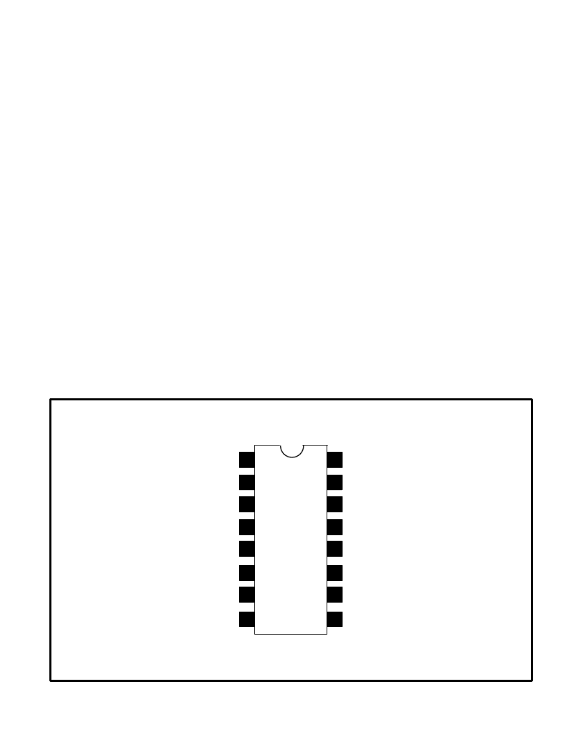
Pin Connection Diagram
Sync Filter
Sync Output
Forward AGC Output
Input GND
1
2
3
4
Max Gain Bias
5
AGC Filter
6
Reverse AGC Output
7
16
15
14
13
AGC Delay
Substrate GND
12
11
(+) 12V Supply
10
Video Input
8
Key Pulse Input
9
相关PDF资料 |
PDF描述 |
|---|---|
| NTE843 | Integrated Circuit TV Video IF Phase Locked Loop (PLL) Synchronous Detector |
| NTE844 | Integrated Circuit Single Chip TV Chroma/Luminance Processor |
| NTE846 | Integrated Circuit TV Video Modulator |
| NTE849 | Integrated Circuit TV Horizontal/Vertical Countdown Digital Sync System |
| NTE851 | Integrated Circuit VHF/UHF Prescaler |
相关代理商/技术参数 |
参数描述 |
|---|---|
| NTE843 | 制造商:NTE Electronics 功能描述:IC-TV VIDEO IF AFT 制造商:NTE Electronics 功能描述:Phase Locked Loop 16-Pin PDIP |
| NTE844 | 制造商:NTE Electronics 功能描述:Single Chip TV Chroma/Luminance Processor 28-Pin PDIP |
| NTE8448 | 制造商:NTE Electronics 功能描述: |
| NTE845 | 制造商:未知厂家 制造商全称:未知厂家 功能描述:Consumer IC |
| NTE846 | 制造商:NTE Electronics 功能描述:IC, VIDEO PROCESO; Video Processor Application:Colour Television Receivers; Supply Voltage Min:12V; Supply Voltage Max:18V; Power Dissipation Pd:1.39W; IC Mounting:Through Hole; TV / Video Case Style:DIP; No. of Pins:18 制造商:NTE Electronics 功能描述:TV Video Modulator 18-Pin PDIP |
发布紧急采购,3分钟左右您将得到回复。