- 您现在的位置:买卖IC网 > Datasheet目录871 > OKR-T/6-W12-C (Murata Power Solutions Inc)CONV DC/DC 6A 12VIN POL SIP Datasheet资料下载
参数资料
| 型号: | OKR-T/6-W12-C |
| 厂商: | Murata Power Solutions Inc |
| 文件页数: | 4/11页 |
| 文件大小: | 0K |
| 描述: | CONV DC/DC 6A 12VIN POL SIP |
| 产品培训模块: | Okami Series |
| 特色产品: | Okami? Series PoL Converters |
| 标准包装: | 360 |
| 系列: | Okami™ OKR-T/6 |
| 类型: | 非隔离(POL) |
| 输出数: | 1 |
| 电压 - 输入(最小): | 4.5V |
| 电压 - 输入(最大): | 14V |
| Voltage - Output 1: | 0.591 ~ 6 V |
| 电流 - 输出(最大): | 6A |
| 电源(瓦) - 制造商系列: | 30W |
| 特点: | 具有远程开/关功能 |
| 安装类型: | 通孔 |
| 封装/外壳: | 5-SIP 模块 |
| 尺寸/尺寸: | 0.41" L x 0.30" W x 0.65" H(10.4mm x 7.6mm x 16.5mm) |
| 包装: | 托盘 |
| 效率: | 95.5% |
| 电源(瓦特)- 最大: | 30W |
| 产品目录页面: | 2720 (CN2011-ZH PDF) |
| 其它名称: | 811-2179 |
�� �
�
�OKR-T/6� Series�
�Adjustable� Output� 6-Amp� SIP-mount� DC/DC� Converters�
�Notes�
�(1)� All� speci?cations� are� typical� unless� noted.� General� conditions� for� Speci?cations� are� +25�
�deg.C,� Vin=nominal,� Vout=nominal� (no� trim� installed),� full� rated� load.� Adequate� air?ow�
�must� be� supplied� for� extended� testing� under� power.�
�All� models� are� tested� and� speci?ed� with� external� 1μF� and� 10� μF� paralleled� ceramic/�
�tantalum� output� capacitors� and� a� 22� μF� external� input� capacitor.� All� capacitors� are� low�
�ESR� types.� Caps� are� layout� dependent� These� capacitors� are� necessary� to� accommodate�
�our� test� equipment� and� may� not� be� required� in� your� applications.� All� models� are� stable�
�and� regulate� within� spec� under� no-load� conditions.�
�(2)� Input� Back� Ripple� Current� is� tested� and� speci?ed� over� a� 5� Hz� to� 20� MHz� bandwidth.� Input�
�?ltering� is� Cin=2� x� 100� μF,� 100V� tantalum,� Cbus=1000� μF,� 100V� electrolytic,� Lbus=1� μH.�
�All� caps� are� low� ESR� types.�
�(3)� Note� that� Maximum� Power� Derating� curves� indicate� an� average� current� at� nominal� input�
�voltage.� At� higher� temperatures� and/or� lower� air?ow,� the� DC/DC� converter� will� tolerate�
�brief� full� current� outputs� if� the� total� RMS� current� over� time� does� not� exceed� the� Derating�
�curve.� All� Derating� curves� are� presented� at� sea� level� altitude.� Be� aware� of� reduced� power�
�dissipation� with� increasing� altitude.�
�(4a)� Mean� Time� Before� Failure� is� calculated� using� the� Telcordia� (Belcore)� SR-332� Method� 1,�
�Case� 3,� ground� ?xed� conditions,� Tpcboard=+25� ?C,� full� output� load,� natural� air� convec-�
�tion.�
�(4b)� Mean� Time� Before� Failure� is� calculated� using� the� MIL-HDBK-217N2� method,� ground�
�benign,� +25oC.,� full� output� load,� natural� convection.�
�(5)� The� On/Off� Control� is� normally� controlled� by� a� switch� or� open� collector� or� open� drain� tran-�
�sistor.� But� it� may� also� be� driven� with� external� logic� or� by� applying� appropriate� external�
�voltages� which� are� referenced� to� Input� Common.�
�(6)� Short� circuit� shutdown� begins� when� the� output� voltage� degrades� approximately� 2%� from�
�the� selected� setting.�
�(7)� The� outputs� are� not� intended� to� sink� appreciable� reverse� current.�
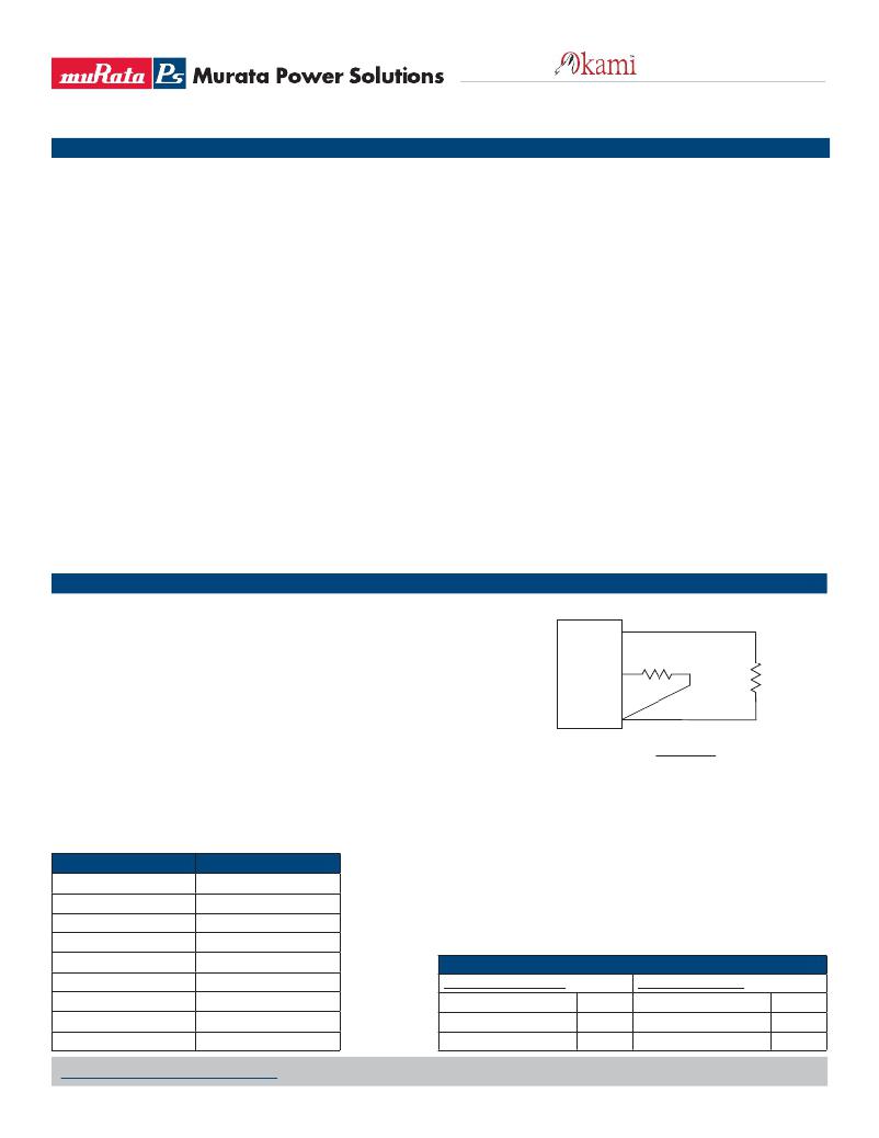
�Trim� Connections�
�Output� Voltage� Adustment�
�The� output� voltage� may� be� adjusted� over� a� limited� range� by� connecting� an�
�(8)� “Hiccup”� overcurrent� operation� repeatedly� attempts� to� restart� the� converter� with� a� brief,�
�full-current� output.� If� the� overcurrent� condition� still� exists,� the� restart� current� will� be�
�removed� and� then� tried� again.� This� short� current� pulse� prevents� overheating� and� damag-�
�ing� the� converter.� Once� the� fault� is� removed,� the� converter� immediately� recovers� normal�
�operation.�
�(9)� Input� Fusing:� If� reverse� polarity� is� accidentally� applied� to� the� input,� to� ensure� reverse�
�input� protection� with� full� output� load,� always� connect� an� external� input� fast-blow� fuse�
�in� series� with� the� +Vin� input.� Use� approximately� twice� the� full� input� current� rating� with�
�nominal� input� voltage.�
�(10)� Regulation� speci?cations� describe� the� deviation� as� the� line� input� voltage� or� output� load�
�current� is� varied� from� a� nominal� midpoint� value� to� either� extreme.�
�(11)� CAUTION:� Since� the� converter� is� mounted� on� the� end� by� its� pins,� do� not� subject� it� to� high�
�vibration,� shock� or� acceleration.�
�(12)� Output� current� limit� and� short� circuit� protection� is� non-latching.� When� the� overcurrent�
�fault� is� removed,� the� converter� will� immediately� recover.�
�(13)� Do� not� exceed� maximum� power� speci?cations� when� adjusting� the� output� trim.� All� pub-�
�lished� speci?cations� are� listed� at� rated� nominal� output� current� using� published� Derating�
�curves.� The� maximum� power� speci?cations� indicate� brief� operation� before� overcurrent�
�shutdown� occurs.� Note� particularly� that� current� must� be� limited� at� higher� output� voltage�
�in� order� to� comply� with� maximum� power� requirements.�
�(14)� At� zero� output� current,� the� output� may� contain� low� frequency� components� which� exceed�
�the� ripple� speci?cation.� The� output� may� be� operated� inde?nitely� with� no� load.�
�(15)� The� input� and� output� are� not� isolated.� They� share� a� single� COMMON� power� and� signal�
�return.�
�(16)� Vin� must� be� 2V� or� higher� than� Vout� for� 3.3� to� 6V� outputs:� Vin� >=� (2V� +� Vout)�
�+V� OUT�
�external� trim� resistor� (Rtrim)� between� the� Trim� pin� and� Ground.� The� Rtrim�
�resistor� must� be� a� 1/10� Watt� precision� metal� ?lm� type,� ±0.5%� accuracy� or�
�better� with� low� temperature� coef?cient,� ±100� ppm/oC.� or� better.� Mount� the�
�Trim�
�R� TRIM�
�R� LOAD�
�resistor� close� to� the� converter� with� very� short� leads� or� use� a� surface� mount�
�trim� resistor.�
�Ground�
�In� the� tables� below,� the� calculated� resistance� is� given.� Do� not� exceed� the�
�speci?ed� limits� of� the� output� voltage� or� the� converter’s� maximum� power�
�rating� when� applying� these� resistors.� Also,� avoid� high� noise� at� the� Trim�
�R� TRIM� (kΩ)� =�
�1.182�
�V� OUT� ?� 0.591�
�R� TRIM� (k� ?� )� =� _____________�
�input.However,to prevent instability,you should never connect any capaci-�
�tors� to� Trim.�
�OKR-T/6-W12�
�Resistor� Trim� Equation,� OKR-T/6-W12� models:�
�1.182�
�(V� OUT� –� 0.591)�
�Output� Voltage�
�6� V.�
�5� V.�
�3.3� V.�
�2.5� V.�
�1.8� V.�
�Calculated� Rtrim� (Ω)�
�218.5�
�268�
�436�
�619�
�978�
�Soldering� Guidelines�
�Murata� Power� Solutions� recommends� the� speci?cations� below� when� installing� these�
�converters.� These� speci?cations� vary� depending� on� the� solder� type.� Exceeding� these�
�speci?cations� may� cause� damage� to� the� product.� Your� production� environment�
�may� differ;� therefore� please� thoroughly� review� these� guidelines� with� your� process�
�engineers.�
�Wave� Solder� Operations� for� through-hole� mounted� products� (THMT)�
�1.5� V.�
�1300�
�For Sn/Ag/Cu based solders:�
�For Sn/Pb based solders:�
�1.2� V.�
�1.0� V.�
�0.591� V.�
�1940�
�2890�
�∞� (open)�
�Maximum� Preheat� Temperature�
�Maximum� Pot� Temperature�
�Maximum� Solder� Dwell� Time�
�115°� C.�
�270°� C.�
�7� seconds�
�Maximum� Preheat� Temperature�
�Maximum� Pot� Temperature�
�Maximum� Solder� Dwell� Time�
�105°� C.�
�250°� C.�
�6� seconds�
�www.murata-ps.com/support�
�MDC_OKR-T/6-W12� Series.B03� Page� 4� of� 11�
�相关PDF资料 |
PDF描述 |
|---|---|
| OKX-T/3-D12N-C | DC-DC CONVRT 0.7525-5.5V 3A 5SIP |
| OKX-T/3-W5P-C | DC-DC CONVRT 0.7525-3.6V 3A 5SIP |
| OKX-T/5-D12P-C | DC-DC CONVRT 0.7525-5.5V 5A 5SIP |
| OKX-T/5-W5P-C | DC-DC CONVRT 0.7525-3.6V 5A 5SIP |
| OKX2-T/16-D12P-C | CONVERT DC/DC SIP 80W 0.75-5.5V |
相关代理商/技术参数 |
参数描述 |
|---|---|
| OKX | 制造商:MURATA-PS 制造商全称:Murata Power Solutions Inc. 功能描述:Adjustable DOSA 10/16-Amp SIP DC/DC Converters |
| OKX2-T/10-D12N-C | 功能描述:DC/DC转换器 12V 0.75-5.5Vout 10A Sequence Neg logic RoHS:否 制造商:Murata 产品: 输出功率: 输入电压范围:3.6 V to 5.5 V 输入电压(标称): 输出端数量:1 输出电压(通道 1):3.3 V 输出电流(通道 1):600 mA 输出电压(通道 2): 输出电流(通道 2): 安装风格:SMD/SMT 封装 / 箱体尺寸: |
| OKX2-T/10-D12P-C | 功能描述:DC/DC转换器 12V 0.75-5.5Vout 10A Sequence Pos logic RoHS:否 制造商:Murata 产品: 输出功率: 输入电压范围:3.6 V to 5.5 V 输入电压(标称): 输出端数量:1 输出电压(通道 1):3.3 V 输出电流(通道 1):600 mA 输出电压(通道 2): 输出电流(通道 2): 安装风格:SMD/SMT 封装 / 箱体尺寸: |
| OKX2-T/10-W5N-C | 功能描述:DC/DC转换器 5Vin .75-3.6Vout 10A RoHS:否 制造商:Murata 产品: 输出功率: 输入电压范围:3.6 V to 5.5 V 输入电压(标称): 输出端数量:1 输出电压(通道 1):3.3 V 输出电流(通道 1):600 mA 输出电压(通道 2): 输出电流(通道 2): 安装风格:SMD/SMT 封装 / 箱体尺寸: |
| OKX2-T/10-W5NJ-C | 功能描述:DC/DC转换器 5Vin .75-3.6Vout 10A RoHS:否 制造商:Murata 产品: 输出功率: 输入电压范围:3.6 V to 5.5 V 输入电压(标称): 输出端数量:1 输出电压(通道 1):3.3 V 输出电流(通道 1):600 mA 输出电压(通道 2): 输出电流(通道 2): 安装风格:SMD/SMT 封装 / 箱体尺寸: |
发布紧急采购,3分钟左右您将得到回复。