- 您现在的位置:买卖IC网 > PDF目录11170 > P80C31SFAA,512 (NXP Semiconductors)IC 80C51 MCU 8BIT ROMLESS 44PLCC PDF资料下载
参数资料
| 型号: | P80C31SFAA,512 |
| 厂商: | NXP Semiconductors |
| 文件页数: | 5/32页 |
| 文件大小: | 0K |
| 描述: | IC 80C51 MCU 8BIT ROMLESS 44PLCC |
| 标准包装: | 26 |
| 系列: | 80C |
| 核心处理器: | 8051 |
| 芯体尺寸: | 8-位 |
| 速度: | 16MHz |
| 连通性: | UART/USART |
| 外围设备: | POR |
| 输入/输出数: | 32 |
| 程序存储器类型: | ROMless |
| RAM 容量: | 128 x 8 |
| 电压 - 电源 (Vcc/Vdd): | 2.7 V ~ 5.5 V |
| 振荡器型: | 内部 |
| 工作温度: | 0°C ~ 70°C |
| 封装/外壳: | 44-LCC(J 形引线) |
| 包装: | 管件 |
第1页第2页第3页第4页当前第5页第6页第7页第8页第9页第10页第11页第12页第13页第14页第15页第16页第17页第18页第19页第20页第21页第22页第23页第24页第25页第26页第27页第28页第29页第30页第31页第32页
Philips Semiconductors
Product specification
80C31/80C32
80C51 8-bit microcontroller family
128/256 byte RAM ROMless low voltage (2.7V–5.5V),
low power, high speed (33 MHz)
2000 Aug 07
13
Baud Rate Generator Mode
Bits TCLK and/or RCLK in T2CON (Table 3) allow the serial port
transmit and receive baud rates to be derived from either Timer 1 or
Timer 2. When TCLK= 0, Timer 1 is used as the serial port transmit
baud rate generator. When TCLK= 1, Timer 2 is used as the serial
port transmit baud rate generator. RCLK has the same effect for the
serial port receive baud rate. With these two bits, the serial port can
have different receive and transmit baud rates – one generated by
Timer 1, the other by Timer 2.
Figure 6 shows the Timer 2 in baud rate generation mode. The baud
rate generation mode is like the auto-reload mode, in that a rollover
in TH2 causes the Timer 2 registers to be reloaded with the 16-bit
value in registers RCAP2H and RCAP2L, which are preset by
software.
The baud rates in modes 1 and 3 are determined by Timer 2’s
overflow rate given below:
Modes 1 and 3 Baud Rates
+ Timer 2 Overflow Rate
16
The timer can be configured for either “timer” or “counter” operation.
In many applications, it is configured for “timer” operation (C/T2*=0).
Timer operation is different for Timer 2 when it is being used as a
baud rate generator.
Usually, as a timer it would increment every machine cycle (i.e., 1/12
the oscillator frequency). As a baud rate generator, it increments
every state time (i.e., 1/2 the oscillator frequency). Thus the baud
rate formula is as follows:
Oscillator Frequency
[32
[65536
* (RCAP2H, RCAP2L)]]
Modes 1 and 3 Baud Rates =
Where:
(RCAP2H, RCAP2L)= The content of RCAP2H and
RCAP2L taken as a 16-bit unsigned integer.
The Timer 2 as a baud rate generator mode shown in Figure 6, is
valid only if RCLK and/or TCLK = 1 in T2CON register. Note that a
rollover in TH2 does not set TF2, and will not generate an interrupt.
Thus, the Timer 2 interrupt does not have to be disabled when
Timer 2 is in the baud rate generator mode. Also if the EXEN2
(T2 external enable flag) is set, a 1-to-0 transition in T2EX
(Timer/counter 2 trigger input) will set EXF2 (T2 external flag) but
will not cause a reload from (RCAP2H, RCAP2L) to (TH2,TL2).
Therefore when Timer 2 is in use as a baud rate generator, T2EX
can be used as an additional external interrupt, if needed.
When Timer 2 is in the baud rate generator mode, one should not try
to read or write TH2 and TL2. As a baud rate generator, Timer 2 is
incremented every state time (osc/2) or asynchronously from pin T2;
under these conditions, a read or write of TH2 or TL2 may not be
accurate. The RCAP2 registers may be read, but should not be
written to, because a write might overlap a reload and cause write
and/or reload errors. The timer should be turned off (clear TR2)
before accessing the Timer 2 or RCAP2 registers.
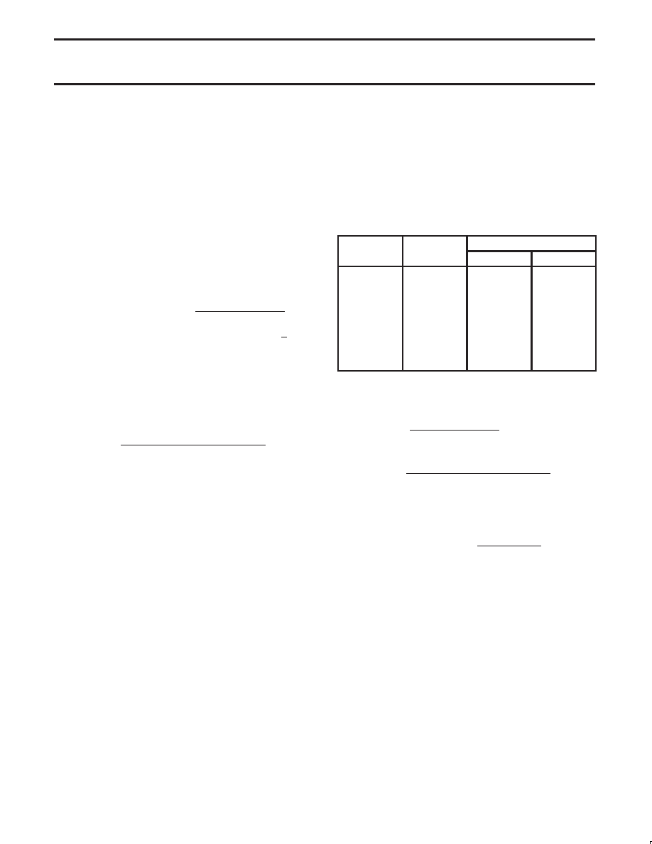
Table 4 shows commonly used baud rates and how they can be
obtained from Timer 2.
Table 4.
Timer 2 Generated Commonly Used
Baud Rates
Ba d Rate
Osc Freq
Timer 2
Baud Rate
Osc Freq
RCAP2H
RCAP2L
375 K
12 MHz
FF
9.6 K
12 MHz
FF
D9
2.8 K
12 MHz
FF
B2
2.4 K
12 MHz
FF
64
1.2 K
12 MHz
FE
C8
300
12 MHz
FB
1E
110
12 MHz
F2
AF
300
6 MHz
FD
8F
110
6 MHz
F9
57
Summary Of Baud Rate Equations
Timer 2 is in baud rate generating mode. If Timer 2 is being clocked
through pin T2(P1.0) the baud rate is:
Baud Rate
+ Timer 2 Overflow Rate
16
If Timer 2 is being clocked internally, the baud rate is:
Baud Rate
+
f
OSC
[32
[65536
* (RCAP2H, RCAP2L)]]
Where fOSC= Oscillator Frequency
To obtain the reload value for RCAP2H and RCAP2L, the above
equation can be rewritten as:
RCAP2H, RCAP2L
+ 65536 *
f
OSC
32
Baud Rate
Timer/Counter 2 Set-up
Except for the baud rate generator mode, the values given for
T2CON do not include the setting of the TR2 bit. Therefore, bit TR2
must be set, separately, to turn the timer on. See Table 5 for set-up
of Timer 2 as a timer. Also see Table 6 for set-up of Timer 2 as a
counter.
相关PDF资料 |
PDF描述 |
|---|---|
| PI5V330AQE | IC VIDEO MUX/DEMUX 2X1 16QSOP |
| PI5A100QE | IC SWITCH QUAD SPDT 16QSOP |
| C8051F334-GM | IC 8051 MCU 2KB FLASH 20QFN |
| VI-BNM-IW-F4 | CONVERTER MOD DC/DC 10V 100W |
| VI-BNM-IW-F3 | CONVERTER MOD DC/DC 10V 100W |
相关代理商/技术参数 |
参数描述 |
|---|---|
| P80C31SFAA-T | 制造商:未知厂家 制造商全称:未知厂家 功能描述:8-Bit Microcontroller |
| P80C31SFBB | 制造商:PHILIPS 制造商全称:NXP Semiconductors 功能描述:80C51 8-bit microcontroller family 4K/128 OTP/ROM/ROMless low voltage 2.7V.5.5V, low power, high speed 33 MHz |
| P80C31SFBB-S | 制造商:未知厂家 制造商全称:未知厂家 功能描述:8-Bit Microcontroller |
| P80C31SFPN | 制造商:PHILIPS 制造商全称:NXP Semiconductors 功能描述:80C51 8-bit microcontroller family 4K/128 OTP/ROM/ROMless low voltage 2.7V.5.5V, low power, high speed 33 MHz |
| P80C31UBAA | 制造商:PHILIPS 制造商全称:NXP Semiconductors 功能描述:80C51 8-bit microcontroller family 4K/128 OTP/ROM/ROMless low voltage 2.7V.5.5V, low power, high speed 33 MHz |
发布紧急采购,3分钟左右您将得到回复。