- 您现在的位置:买卖IC网 > PDF目录11170 > P80C31SFAA,512 (NXP Semiconductors)IC 80C51 MCU 8BIT ROMLESS 44PLCC PDF资料下载
参数资料
| 型号: | P80C31SFAA,512 |
| 厂商: | NXP Semiconductors |
| 文件页数: | 6/32页 |
| 文件大小: | 0K |
| 描述: | IC 80C51 MCU 8BIT ROMLESS 44PLCC |
| 标准包装: | 26 |
| 系列: | 80C |
| 核心处理器: | 8051 |
| 芯体尺寸: | 8-位 |
| 速度: | 16MHz |
| 连通性: | UART/USART |
| 外围设备: | POR |
| 输入/输出数: | 32 |
| 程序存储器类型: | ROMless |
| RAM 容量: | 128 x 8 |
| 电压 - 电源 (Vcc/Vdd): | 2.7 V ~ 5.5 V |
| 振荡器型: | 内部 |
| 工作温度: | 0°C ~ 70°C |
| 封装/外壳: | 44-LCC(J 形引线) |
| 包装: | 管件 |
第1页第2页第3页第4页第5页当前第6页第7页第8页第9页第10页第11页第12页第13页第14页第15页第16页第17页第18页第19页第20页第21页第22页第23页第24页第25页第26页第27页第28页第29页第30页第31页第32页
Philips Semiconductors
Product specification
80C31/80C32
80C51 8-bit microcontroller family
128/256 byte RAM ROMless low voltage (2.7V–5.5V),
low power, high speed (33 MHz)
2000 Aug 07
14
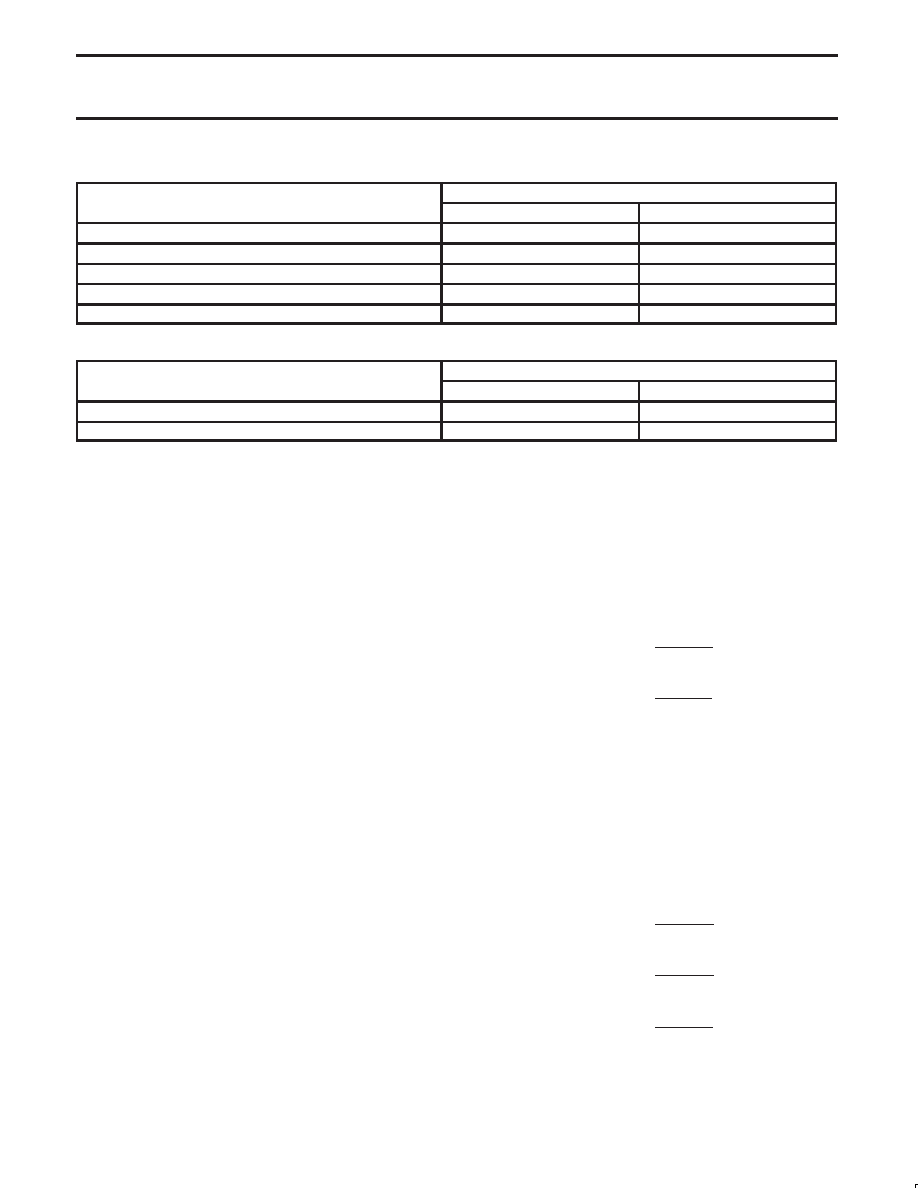
Table 5. Timer 2 as a Timer
MODE
T2CON
MODE
INTERNAL CONTROL (Note 1)
EXTERNAL CONTROL (Note 2)
16-bit Auto-Reload
00H
08H
16-bit Capture
01H
09H
Baud rate generator receive and transmit same baud rate
34H
36H
Receive only
24H
26H
Transmit only
14H
16H
Table 6. Timer 2 as a Counter
MODE
TMOD
MODE
INTERNAL CONTROL (Note 1)
EXTERNAL CONTROL (Note 2)
16-bit
02H
0AH
Auto-Reload
03H
0BH
NOTES:
1. Capture/reload occurs only on timer/counter overflow.
2. Capture/reload occurs on timer/counter overflow and a 1-to-0 transition on T2EX (P1.1) pin except when Timer 2 is used in the baud rate
generator mode.
Enhanced UART
The UART operates in all of the usual modes that are described in
the first section of
Data Handbook IC20, 80C51-Based 8-Bit
Microcontrollers. In addition the UART can perform framing error
detect by looking for missing stop bits, and automatic address
recognition. The 80C31/32 UART also fully supports multiprocessor
communication.
When used for framing error detect the UART looks for missing stop
bits in the communication. A missing bit will set the FE bit in the
SCON register. The FE bit shares the SCON.7 bit with SM0 and the
function of SCON.7 is determined by PCON.6 (SMOD0) (see
Figure 7). If SMOD0 is set then SCON.7 functions as FE. SCON.7
functions as SM0 when SMOD0 is cleared. When used as FE
SCON.7 can only be cleared by software. Refer to Figure 8.
Automatic Address Recognition
Automatic Address Recognition is a feature which allows the UART
to recognize certain addresses in the serial bit stream by using
hardware to make the comparisons. This feature saves a great deal
of software overhead by eliminating the need for the software to
examine every serial address which passes by the serial port. This
feature is enabled by setting the SM2 bit in SCON. In the 9 bit UART
modes, mode 2 and mode 3, the Receive Interrupt flag (RI) will be
automatically set when the received byte contains either the “Given”
address or the “Broadcast” address. The 9 bit mode requires that
the 9th information bit is a 1 to indicate that the received information
is an address and not data. Automatic address recognition is shown
in Figure 9.
The 8 bit mode is called Mode 1. In this mode the RI flag will be set
if SM2 is enabled and the information received has a valid stop bit
following the 8 address bits and the information is either a Given or
Broadcast address.
Mode 0 is the Shift Register mode and SM2 is ignored.
Using the Automatic Address Recognition feature allows a master to
selectively communicate with one or more slaves by invoking the
Given slave address or addresses. All of the slaves may be
contacted by using the Broadcast address. Two special Function
Registers are used to define the slave’s address, SADDR, and the
address mask, SADEN. SADEN is used to define which bits in the
SADDR are to b used and which bits are “don’t care”. The SADEN
mask can be logically ANDed with the SADDR to create the “Given”
address which the master will use for addressing each of the slaves.
Use of the Given address allows multiple slaves to be recognized
while excluding others. The following examples will help to show the
versatility of this scheme:
Slave 0
SADDR
=
1100 0000
SADEN
=
1111 1101
Given
=
1100 00X0
Slave 1
SADDR
=
1100 0000
SADEN
=
1111 1110
Given
=
1100 000X
In the above example SADDR is the same and the SADEN data is
used to differentiate between the two slaves. Slave 0 requires a 0 in
bit 0 and it ignores bit 1. Slave 1 requires a 0 in bit 1 and bit 0 is
ignored. A unique address for Slave 0 would be 1100 0010 since
slave 1 requires a 0 in bit 1. A unique address for slave 1 would be
1100 0001 since a 1 in bit 0 will exclude slave 0. Both slaves can be
selected at the same time by an address which has bit 0 = 0 (for
slave 0) and bit 1 = 0 (for slave 1). Thus, both could be addressed
with 1100 0000.
In a more complex system the following could be used to select
slaves 1 and 2 while excluding slave 0:
Slave 0
SADDR
=
1100 0000
SADEN
=
1111 1001
Given
=
1100 0XX0
Slave 1
SADDR
=
1110 0000
SADEN
=
1111 1010
Given
=
1110 0X0X
Slave 2
SADDR
=
1110 0000
SADEN
=
1111 1100
Given
=
1110 00XX
In the above example the differentiation among the 3 slaves is in the
lower 3 address bits. Slave 0 requires that bit 0 = 0 and it can be
uniquely addressed by 1110 0110. Slave 1 requires that bit 1 = 0 and
it can be uniquely addressed by 1110 and 0101. Slave 2 requires
that bit 2 = 0 and its unique address is 1110 0011. To select Slaves 0
相关PDF资料 |
PDF描述 |
|---|---|
| PI5V330AQE | IC VIDEO MUX/DEMUX 2X1 16QSOP |
| PI5A100QE | IC SWITCH QUAD SPDT 16QSOP |
| C8051F334-GM | IC 8051 MCU 2KB FLASH 20QFN |
| VI-BNM-IW-F4 | CONVERTER MOD DC/DC 10V 100W |
| VI-BNM-IW-F3 | CONVERTER MOD DC/DC 10V 100W |
相关代理商/技术参数 |
参数描述 |
|---|---|
| P80C31SFAA-T | 制造商:未知厂家 制造商全称:未知厂家 功能描述:8-Bit Microcontroller |
| P80C31SFBB | 制造商:PHILIPS 制造商全称:NXP Semiconductors 功能描述:80C51 8-bit microcontroller family 4K/128 OTP/ROM/ROMless low voltage 2.7V.5.5V, low power, high speed 33 MHz |
| P80C31SFBB-S | 制造商:未知厂家 制造商全称:未知厂家 功能描述:8-Bit Microcontroller |
| P80C31SFPN | 制造商:PHILIPS 制造商全称:NXP Semiconductors 功能描述:80C51 8-bit microcontroller family 4K/128 OTP/ROM/ROMless low voltage 2.7V.5.5V, low power, high speed 33 MHz |
| P80C31UBAA | 制造商:PHILIPS 制造商全称:NXP Semiconductors 功能描述:80C51 8-bit microcontroller family 4K/128 OTP/ROM/ROMless low voltage 2.7V.5.5V, low power, high speed 33 MHz |
发布紧急采购,3分钟左右您将得到回复。