- 您现在的位置:买卖IC网 > PDF目录11176 > P87LPC764FDH,512 (NXP Semiconductors)IC 80C51 MCU 4KB OTP 20TSSOP PDF资料下载
参数资料
| 型号: | P87LPC764FDH,512 |
| 厂商: | NXP Semiconductors |
| 文件页数: | 8/60页 |
| 文件大小: | 0K |
| 描述: | IC 80C51 MCU 4KB OTP 20TSSOP |
| 标准包装: | 75 |
| 系列: | LPC700 |
| 核心处理器: | 8051 |
| 芯体尺寸: | 8-位 |
| 速度: | 20MHz |
| 连通性: | I²C,UART/USART |
| 外围设备: | 欠压检测/复位,LED,POR,WDT |
| 输入/输出数: | 18 |
| 程序存储器容量: | 4KB(4K x 8) |
| 程序存储器类型: | OTP |
| RAM 容量: | 128 x 8 |
| 电压 - 电源 (Vcc/Vdd): | 2.7 V ~ 6 V |
| 振荡器型: | 内部 |
| 工作温度: | -40°C ~ 85°C |
| 封装/外壳: | 20-TSSOP(0.173",4.40mm 宽) |
| 包装: | 管件 |
第1页第2页第3页第4页第5页第6页第7页当前第8页第9页第10页第11页第12页第13页第14页第15页第16页第17页第18页第19页第20页第21页第22页第23页第24页第25页第26页第27页第28页第29页第30页第31页第32页第33页第34页第35页第36页第37页第38页第39页第40页第41页第42页第43页第44页第45页第46页第47页第48页第49页第50页第51页第52页第53页第54页第55页第56页第57页第58页第59页第60页
Philips Semiconductors
Product data
P87LPC764
Low power, low price, low pin count (20 pin)
microcontroller with 4 kbyte OTP
2003 Sep 03
15
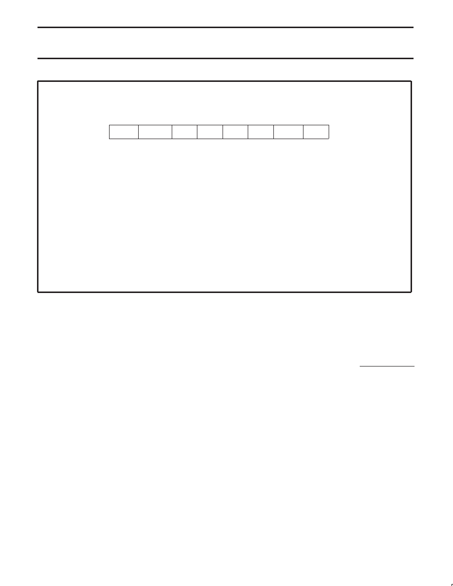
BIT
SYMBOL
FUNCTION
I2CFG.7
SLAVEN
Slave Enable. Writing a 1 this bit enables the slave functions of the I2C subsystem. If SLAVEN and
MASTRQ are 0, the I2C hardware is disabled. This bit is cleared to 0 by reset and by an I2C
time-out.
I2CFG.6
MASTRQ
Master Request. Writing a 1 to this bit requests mastership of the I2C bus. If a transmission is in
progress when this bit is changed from 0 to 1, action is delayed until a stop condition is detected. A
start condition is sent and DRDY is set (thus making ATN = 1 and generating an I2C interrupt).
When a master wishes to release mastership status of the I2C, it writes a 1 to XSTP in I2CON.
MASTRQ is cleared by an I2C time-out.
I2CFG.5
CLRTI
Writing a 1 to this bit clears the Timer I overflow flag. This bit position always reads as a 0.
I2CFG.4
TIRUN
Writing a 1 to this bit lets Timer I run; a zero stops and clears it. Together with SLAVEN, MASTRQ,
and MASTER, this bit determines operational modes as shown in Table 1.
I2CFG.2, 3
—
Reserved for future use. Should not be set to 1 by user programs.
I2CFG.1, 0 CT1, CT0
These two bits are programmed as a function of the CPU clock rate, to optimize the MIN HI and LO
time of SCL when this device is a master on the I2C. The time value determined by these bits
controls both of these parameters, and also the timing for stop and start conditions.
CT0
SU01474
CT1
—
TIRUN
CLRTI
MASTRQ
SLAVEN
0
1
2
3
4
5
6
7
I2CFG
Reset Value: 00h
Bit Addressable
Address: C8h
Figure 8. I2C Configuration Register (I2CFG)
Regarding Software Response Time
Because the P87LPC764 can run at 20 MHz, and because the I2C
interface is optimized for high-speed operation, it is quite likely that
an I2C service routine will sometimes respond to DRDY (which is set
at a rising edge of SCL) and write I2DAT before SCL has gone low
again. If XDAT were applied directly to SDA, this situation would
produce an I2C protocol violation. The programmer need not worry
about this possibility because XDAT is applied to SDA only when
SCL is low.
Conversely, a program that includes an I2C service routine may take
a long time to respond to DRDY. Typically, an I2C routine operates
on a flag-polling basis during a message, with interrupts from other
peripheral functions enabled. If an interrupt occurs, it will delay the
response of the I2C service routine. The programmer need not worry
about this very much either, because the I2C hardware stretches the
SCL low time until the service routine responds. The only constraint
on the response is that it must not exceed the Timer I time-out.
Values to be used in the CT1 and CT0 bits are shown in Table 2. To
allow the I2C bus to run at the maximum rate for a particular
oscillator frequency, compare the actual oscillator rate to the f OSC
max column in the table. The value for CT1 and CT0 is found in the
first line of the table where CPU clock max is greater than or equal
to the actual frequency.
Table 2 also shows the machine cycle count for various settings of
CT1/CT0. This allows calculation of the actual minimum high and
low times for SCL as follows:
SCL min high low time (in microseconds)
+ 6 * Min Time Count
CPU clock (in MHz)
For instance, at an 8 MHz frequency, with CT1/CT0 set to 1 0, the
minimum SCL high and low times will be 5.25
s.
Table 2 also shows the Timer I timeout period (given in machine
cycles) for each CT1/CT0 combination. The timeout period varies
because of the way in which minimum SCL high and low times are
measured. When the I2C interface is operating, Timer I is pre-loaded
at every SCL transition with a value dependent upon CT1/CT0. The
pre-load value is chosen such that a minimum SCL high or low time
has elapsed when Timer I reaches a count of 008 (the actual value
pre-loaded into Timer I is 8 minus the machine cycle count).
相关PDF资料 |
PDF描述 |
|---|---|
| VE-B6P-IX | CONVERTER MOD DC/DC 13.8V 75W |
| VE-JNK-IW-F2 | CONVERTER MOD DC/DC 40V 100W |
| VE-JNK-IW-F1 | CONVERTER MOD DC/DC 40V 100W |
| C8051F303-GMR | IC 8051 MCU 8K FLASH 11QFN |
| VE-JNJ-IW-F4 | CONVERTER MOD DC/DC 36V 100W |
相关代理商/技术参数 |
参数描述 |
|---|---|
| P87LPC764FN | 制造商:NXP Semiconductors 功能描述:IC 8BIT MCU 87LC764 DIP20 制造商:NXP Semiconductors 功能描述:IC, 8BIT MCU, 87LC764, DIP20 制造商:NXP Semiconductors 功能描述:IC, 8BIT MCU, 87LC764, DIP20; Controller Family/Series:(8051) 8052; Core Size:8bit; No. of I/O's:18; Supply Voltage Min:2.7V; Supply Voltage Max:6V; Digital IC Case Style:DIP; No. of Pins:20; Program Memory Size:4KB; EEPROM Memory ;RoHS Compliant: Yes 制造商:NXP Semiconductors 功能描述:MCU 8-Bit 87LP 80C51 CISC 4KB EPROM 5V 20-Pin PDIP |
| P87LPC764FN,112 | 功能描述:8位微控制器 -MCU 80C51 4K/128 OTP RoHS:否 制造商:Silicon Labs 核心:8051 处理器系列:C8051F39x 数据总线宽度:8 bit 最大时钟频率:50 MHz 程序存储器大小:16 KB 数据 RAM 大小:1 KB 片上 ADC:Yes 工作电源电压:1.8 V to 3.6 V 工作温度范围:- 40 C to + 105 C 封装 / 箱体:QFN-20 安装风格:SMD/SMT |
| P87LPC764FN112 | 制造商:NXP Semiconductors 功能描述:IC 8BIT MCU 80C51 20MHZ DIP-20 |
| P87LPC764HDH | 制造商:PHILIPS 制造商全称:NXP Semiconductors 功能描述:Low power, low price, low pin count (20 pin) microcontroller with 4 kbyte OTP |
| P87LPC767 | 制造商:PHILIPS 制造商全称:NXP Semiconductors 功能描述:Low power, low price, low pin count 20 pin microcontroller with 4-kbyte OTP and 8-bit A/D converter |
发布紧急采购,3分钟左右您将得到回复。