- 您现在的位置:买卖IC网 > Datasheet目录240 > PAXLSG00 (Red Lion Controls)METER STRAIN GAGE 3 1/2-DIGIT Datasheet资料下载
参数资料
| 型号: | PAXLSG00 |
| 厂商: | Red Lion Controls |
| 文件页数: | 5/8页 |
| 文件大小: | 0K |
| 描述: | METER STRAIN GAGE 3 1/2-DIGIT |
| 标准包装: | 1 |
| 系列: | PAX®LITE |
| 类型: | 应力测量仪,毫伏表 |
| 测量范围: | ±2V |
| 显示器样式: | 红色字符,黑色背景 |
| 显示器类型: | LED |
| 显示器正面尺寸: | 3.80" L x 1.95" W(96.5 x 49.5mm) |
| 显示器位数: | 3.5 |
| 显示器位数 - 高度: | 0.560"(14.22mm) |
| 安装类型: | 面板安装 |
| 端子: | 端接块 |
| 电源电压: | 85 ~ 250VAC |
| 其它名称: | RLC114 |
�� �
�
�3.0� W� IRING�
�THE�
�M� ETER�
�WIRING� OVERVIEW�
�Electrical� connections� are� made� via� screw-clamp� terminals� located� on� the�
�back� of� the� meter.� All� conductors� should� conform� to� the� meter� ’s� voltage� and�
�current� ratings.� All� cabling� should� conform� to� appropriate� standards� of� good�
�installation,� local� codes� and� regulations.� It� is� recommended� that� power� supplied�
�to� the� meter� (AC)� be� protected� by� a� fuse� or� circuit� breaker.�
�When� wiring� the� meter,� compare� the� numbers� embossed� on� the� back� of� the�
�meter� case� against� those� shown� in� wiring� drawings� for� proper� wire� position.� Strip�
�the� wire,� leaving� approximately� 0.3"� (7.5� mm)� bare� lead� exposed� (stranded� wires�
�should� be� tinned� with� solder).� Insert� the� lead� under� the� correct� screw-clamp�
�terminal� and� tighten� until� the� wire� is� secure.� (Pull� wire� to� verify� tightness.)�
�EMC� INSTALLATION� GUIDELINES�
�Although� this� meter� is� designed� with� a� high� degree� of� immunity� to� Electro-�
�Magnetic� Interference� (EMI),� proper� installation� and� wiring� methods� must� be�
�followed� to� ensure� compatibility� in� each� application.� The� type� of� the� electrical�
�noise,� its� source� or� the� method� of� coupling� into� the� unit� may� be� different� for�
�various� installations.� Listed� below� are� some� EMC� guidelines� for� successful�
�installation� in� an� industrial� environment.�
�1.� The� meter� should� be� mounted� in� a� metal� enclosure,� which� is� properly�
�connected� to� protective� earth.�
�2.� Never� run� Signal� or� Control� cables� in� the� same� conduit� or� raceway� with� AC�
�power� lines,� conductors� feeding� motors,� solenoids,� SCR� controls,� and�
�heaters,� etc.� The� cables� should� be� run� in� metal� conduit� that� is� properly�
�grounded.� This� is� especially� useful� in� applications� where� cable� runs� are� long�
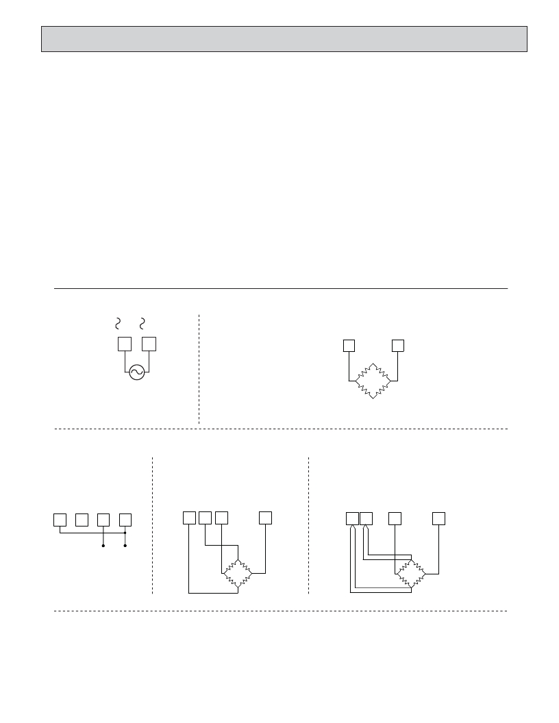
�3.1� POWER� WIRING�
�and� portable� two-way� radios� are� used� in� close� proximity� or� if� the� installation�
�is� near� a� commercial� radio� transmitter.�
�3.� Signal� or� Control� cables� within� an� enclosure� should� be� routed� as� far� away� as�
�possible� from� contactors,� control� relays,� transformers,� and� other� noisy�
�components.�
�4.� In� extremely� high� EMI� environments,� the� use� of� external� EMI� suppression�
�devices,� such� as� ferrite� suppression� cores,� is� effective.� Install� them� on� Signal�
�and� Control� cables� as� close� to� the� unit� as� possible.� Loop� the� cable� through� the�
�core� several� times� or� use� multiple� cores� on� each� cable� for� additional� protection.�
�Install� line� filters� on� the� power� input� cable� to� the� unit� to� suppress� power� line�
�interference.� Install� them� near� the� power� entry� point� of� the� enclosure.� The�
�following� EMI� suppression� devices� (or� equivalent)� are� recommended:�
�Ferrite� Suppression� Cores� for� signal� and� control� cables:�
�Fair-Rite� #� 0443167251� (RLC� #FCOR0000)�
�TDK� #� ZCAT3035-1330A�
�Steward� #28B2029-0A0�
�Line� Filters� for� input� power� cables:�
�Schaffner� #� FN2010-1/07� (RLC� #LFIL0000)�
�Schaffner� #� FN670-1.8/07�
�Corcom� #1VR3�
�Note:� Reference� manufacturer� ’s� instructions� when� installing� a� line� filter.�
�5.� Long� cable� runs� are� more� susceptible� to� EMI� pickup� than� short� cable� runs.�
�Therefore,� keep� cable� runs� as� short� as� possible.�
�6.� Switching� of� inductive� loads� produces� high� EMI.� Use� of� snubbers� across�
�inductive� loads� suppresses� EMI.�
�Snubber:� RLC#SNUB0000.�
�AC� Power�
�Terminal� 1:� VAC�
�Excitation� Power�
�Terminal� 3:� Common�
�Terminal� 2:� VAC�
�1�
�2�
�Terminal� 4:� Excitation� +�
�3�
�4�
�85-250� VAC�
�-EXC.�
�BRIDGE�
�+EXC.�
�5� VDC� @� 60� mA� max,� ±2%�
�10� VDC� @� 120� mA� max,� ±2%�
�3.2� INPUT� SIGNAL� WIRING�
�2-Wire� Single� Ended� Input�
�4-Wire� Bridge� Input�
�6-Wire� Bridge� Input�
�3�
�4�
�5�
�6�
�3�
�4�
�5�
�6�
�3� 4�
�5�
�6�
�+�
�-�
�+EXC.�
�+SEN�
�+EXC.�
�+SIG.�
�-SIG.�
�+SIG.�
�-SIG.�
�-SEN�
�-EXC.�
�DEADLOAD� COMPENSATION�
�In� some� cases,� the� combined� deadload� and� liveload� output� may� exceed� the�
�range� of� the� input.� To� use� this� range,� the� output� of� the� bridge� can� be� offset� a�
�small� amount� by� applying� a� fixed� resistor� across� one� arm� of� the� bridge.� This�
�shifts� the� electrical� output� of� the� bridge� downward� to� within� the� operating� range�
�of� the� meter.� A� 100� K� ohm� fixed� resistor� shifts� the� bridge� output� approximately�
�-10� mV� (350� ohm� bridge,� 10� V� excitation).�
�Connect� the� resistor� between� +SIG� and� -SIG.� Use� a� metal� film� resistor� with�
�a� low� temperature� coefficient� of� resistance.�
�5�
�-EXC.�
�BRIDGE� COMPLETION� RESISTORS�
�For� single� strain� gage� applications,� bridge� completion� resistors� must� be�
�employed� externally� to� the� meter.� Only� use� metal� film� resistors� with� a� low�
�temperature� coefficient� of� resistance.�
�Load� cells� and� pressure� transducers� are� normally� implemented� as� full�
�resistance� bridges� and� do� not� require� bridge� completion� resistors.�
�相关PDF资料 |
PDF描述 |
|---|---|
| PAXLTC00 | METER THERMOCOUPLE 4-DIGIT |
| PAXLVA00 | VOLTMETER AC 3 1/2-DIGIT |
| PAXLVD00 | VOLTMETER DC 3 1/2-DIGIT |
| PAXTM100 | TIMER DISPLAY 1/8 DIN PRESET 6 D |
| PB-1583-TF | BOX ABS 4.37X3.12X2" BK 1=10PCS |
相关代理商/技术参数 |
参数描述 |
|---|---|
| PAXLT000 | 制造商:Red Lion Controls 功能描述:METER, TC/RTD TEMP WITH DUAL RELAY 制造商:Red Lion Controls 功能描述:TC/RTD TEMP WITH DUAL RELAY |
| PAXLT0U0 | 制造商:Red Lion Controls 功能描述:METER, UL LISTED TC/RTD TEMP W/ D RELAY 制造商:Red Lion Controls 功能描述:UL LISTED TC/RTD TEMP WITH DUAL |
| PAXLTC00 | 功能描述:METER THERMOCOUPLE 4-DIGIT RoHS:否 类别:工业控制,仪表 >> 仪表 - 面板,数字 系列:PAX®LITE 标准包装:12 系列:* 其它名称:Q7072030 |
| PAXLVA00 | 功能描述:VOLTMETER AC 3 1/2-DIGIT RoHS:是 类别:工业控制,仪表 >> 仪表 - 面板,数字 系列:PAX®LITE 标准包装:12 系列:* 其它名称:Q7072030 |
| PAXLVD00 | 功能描述:VOLTMETER DC 3 1/2-DIGIT RoHS:是 类别:工业控制,仪表 >> 仪表 - 面板,数字 系列:PAX®LITE 标准包装:12 系列:* 其它名称:Q7072030 |
发布紧急采购,3分钟左右您将得到回复。