- 您现在的位置:买卖IC网 > PDF目录65835 > PBL3770ASOT (ERICSSON POWER MODULES AB) STEPPER MOTOR CONTROLLER, 1.8 A, PDSO20 PDF资料下载
参数资料
| 型号: | PBL3770ASOT |
| 厂商: | ERICSSON POWER MODULES AB |
| 元件分类: | 运动控制电子 |
| 英文描述: | STEPPER MOTOR CONTROLLER, 1.8 A, PDSO20 |
| 封装: | SO-20 |
| 文件页数: | 5/8页 |
| 文件大小: | 140K |
| 代理商: | PBL3770ASOT |
PBL 3770A
5
Functional Description
The PBL 3770A is intended to drive a
bipolar constant current through one
winding of a 2-phase stepper motor.
Current control is achieved through
switched-mode regulation, see figure 5
and 6.
Three different current levels and zero
current can be selected by the input
logic.
The circuit contains the following
functional blocks:
Input logic
Current sense
Single-pulse generator
Output stage
Input logic
Phase input. The phase input
determines the direction of the current in
the motor winding. High input forces the
current from terminal M
A to MB and low
input from terminal M
B to MA. A Schmitt
trigger provides noise immunity and a
delay circuit eliminates the risk of cross
conduction in the output stage during a
phase shift.
Half- and full-step operation is
possible.
Current level selection. The status of I
0
and I
1 inputs determines the current level
in the motor winding. Three fixed current
levels can be selected according to the
table below.
Motor current
I
0
I
1
High level
100%
L
Medium level
60%
H
L
Low level
20%
L
H
Zero current
0%
H
The specific values of the different
current levels are determined by the
reference voltage V
R together with the
value of the sensing resistor R
S.
The peak motor current can be
calculated as follows:
i
m = (VR 0.080) / RS [A],
at 100% level
The motor current can also be
continuously varied by modulating the
voltage reference input.
Current sensor
The current sensor contains a reference
voltage divider and three comparators
for measuring each of the selectable
current levels. The motor current is
sensed as a voltage drop across the
current sensing resistor, R
S, and
compared with one of the voltage
references from the divider. When the
two voltages are equal, the compara-tor
triggers the single-pulse generator. Only
one comparator at a time is activa-ted by
the input logic.
Single-pulse generator
The pulse generator is a monostable
multivibrator triggered on the positive
edge of the comparator output. The
multivibrator output is high during the
pulse time, t
off , which is determined by
the timing components R
T and CT.
t
off = 0.69 RT CT
The single pulse switches off the
power feed to the motor winding,
causing the winding to decrease during
t
off .
If a new trigger signal should occur
during t
off , it is ignored.
Output stage
The output stage contains four
transistors and two diodes, connected in
an H-bridge. Note that the upper
recirculation diodes are connected to the
circuit externally. The two sinking
transistors are used to switch the power
supplied to the motor winding, thus
driving a constant current through the
winding. See figures 5 and 6.
Overload protection
The circuit is equipped with a thermal
shut-down function, which will limit the
junction temperature. The output current
will be reduced if the maximum permis-
sible junction temperature is exceeded.
It should be noted, however, that it is not
short circuit protected.
Operation
When a voltage V
MM is applied across
the motor winding, the current rise
follows the equation:
i
m = (VMM / R) (1 - e
-(R t ) / L )
R = Winding resistance
L = Winding inductance
t
= time
(see figure 6, arrow 1)
The motor current appears across the
external sensing resistor, R
S, as an
analog voltage. This voltage is fed
through a low-pass filter, R
CCC, to the
voltage comparator input (pin 10). At the
moment the sensed voltage rises above
the comparator threshold voltage, the
monostable is triggered and its output
turns off the conducting sink transistor.
The polarity across the motor winding
reverses and the current is forced to
circulate through the appropriate upper
protection diode back through the source
transistor (see figure 6, arrow 2).
After the monostable has timed out,
the current has decayed and the analog
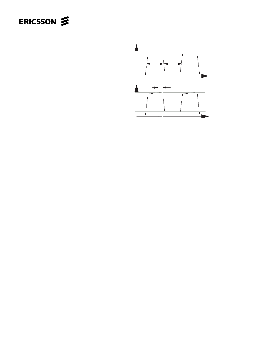
Figure 4. Definition of terms.
| V
– V
|
1/2
1
V
CH
t
on
t
off
f =
s
t
on
t
off
+
Normalized
V
E
MA
MB
td
t
V
CM
V
CL
D =
t
on
t
off
+
1
t
on
相关PDF资料 |
PDF描述 |
|---|---|
| PBL3770ASOS | STEPPER MOTOR CONTROLLER, 1.8 A, PDSO20 |
| PBL3770AQNT | STEPPER MOTOR CONTROLLER, 1.8 A, PQCC28 |
| PBL3770AQNS | STEPPER MOTOR CONTROLLER, 1.8 A, PQCC28 |
| PBL3770ANS | STEPPER MOTOR CONTROLLER, 1.8 A, PDIP16 |
| PBL3773/1QNT | STEPPER MOTOR CONTROLLER, 0.85 A, PQCC28 |
相关代理商/技术参数 |
参数描述 |
|---|---|
| PBL3771 | 制造商:ERICSSON 制造商全称:Ericsson 功能描述:Precision Stepper Motor Driver |
| PBL3771/1NS | 制造商:ERICSSON 制造商全称:Ericsson 功能描述:Precision Stepper Motor Driver |
| PBL3771/1QNS | 制造商:ERICSSON 制造商全称:Ericsson 功能描述:Precision Stepper Motor Driver |
| PBL3771/1QNT | 制造商:ERICSSON 制造商全称:Ericsson 功能描述:Precision Stepper Motor Driver |
| PBL3771/1SOS | 制造商:ERICSSON 制造商全称:Ericsson 功能描述:Precision Stepper Motor Driver |
发布紧急采购,3分钟左右您将得到回复。