- 您现在的位置:买卖IC网 > PDF目录296796 > PCM3794RHBTG4 (TEXAS INSTRUMENTS INC) SPECIALTY TELECOM CIRCUIT, PQCC32 PDF资料下载
参数资料
| 型号: | PCM3794RHBTG4 |
| 厂商: | TEXAS INSTRUMENTS INC |
| 元件分类: | 通信及网络 |
| 英文描述: | SPECIALTY TELECOM CIRCUIT, PQCC32 |
| 封装: | 5 X 5 MM, GREEN, PLASTIC, QFN-32 |
| 文件页数: | 13/67页 |
| 文件大小: | 1417K |
| 代理商: | PCM3794RHBTG4 |
第1页第2页第3页第4页第5页第6页第7页第8页第9页第10页第11页第12页当前第13页第14页第15页第16页第17页第18页第19页第20页第21页第22页第23页第24页第25页第26页第27页第28页第29页第30页第31页第32页第33页第34页第35页第36页第37页第38页第39页第40页第41页第42页第43页第44页第45页第46页第47页第48页第49页第50页第51页第52页第53页第54页第55页第56页第57页第58页第59页第60页第61页第62页第63页第64页第65页第66页第67页
www.ti.com
Power-Supply Current
SLES193C – AUGUST 2006 – REVISED FEBRUARY 2007
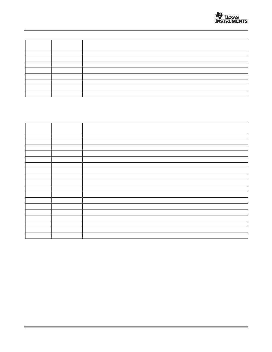
Table 3. Recommended Power-On Sequence (continued)
STEP
REGISTER
NOTE
SETTINGS
17
4C03h
Speaker amplifier shut down release
18
4A01h
VCOM power up
19
523Fh
Analog front end (ADL, ADR, D2S, MCB, PG1, 2, 5, 6) power up
20
5711h
Analog input (MUX3, MUX4) select. Analog input (MUX1, MUX2) select
21
4F0Ch
Analog input L-ch (PG3) volume (0 dB)(2)
22
500Ch
Analog input R-ch (PG4) volume (0 dB)(2)
23
–
Any settings for other devices or wait time(4)(5)
24
49FFh
Speaker amplifier (SPL, SPR) power up (5)
(4)
The PCM3793 requires time for VCOM to reach the common level from GND level. The delay depends on the capacitor value for VCOM
and the setting of register 90 CMT[1:0]. Wait time [s] = 4
× C
VCOM× RCMT
(5)
The PCM3794 does not require this setting because it has no speaker output.
Table 4. Recommended Power-Off Sequence
STEP
REGISTER
NOTE
SETTINGS
1
447Fh
DAC L-ch digital soft-mute enable(1)
2
457Fh
DAC R-ch digital soft-mute enable(1)
3
5132h
ADC L-ch/R-ch digital soft-mute enable, ADC audio interface format (left-justified)(2)
4
5811h
Analog mixer input (SW2, SW5) Select
5
49FFh
Headphone amplifier (HPL, HPR, HPC) power up (4), speaker amplifier (SPL, SPR) power up(3)(4)
6
5200h
Analog front end (ADL, ADR, D2S, MCB, PG1, 2, 5, 6) power down
7
5A10h
VCOM ramp up/down time control, PG1, PG2 gain control (0 dB)
8
4A00h
VCOM power down
9
–
Wait time (100 ms)
10
5A00h
VCOM ramp up/down time control
11
–
Wait time (100 ms)
12
5A20h
VCOM ramp up/down time control
13
–
Wait time (4000 ms)
14
5A30h
VCOM ramp up/down time control
15
49E0h
Headphone amplifier (HPL, HPR, HPC) power down, speaker amplifier (SPL, SPR) power down
16
4800h
Analog mixer (MXL, MXR) power down
17
4900h
DAC (DAL, DAR) and analog bias power down
18
–
Turn off all power supplies(5)
(1)
Any level is acceptable for volume or attenuation.
(2)
Audio interface format should be set according to DSP or decoder.
(3)
PCM3794 has no speaker amplifier.
(4)
These modules must be powered up during the power-down sequence.
(5)
Power supply sequencing is not required. It is recommended to turn off all power supply after register settings with system clock input.
The current consumption of the PCM3793/94 depends on power up/down status of each circuit module. In order
to reduce the power consumption, disabling each module is recommended when it is not used in an application
or operation. Table 5 shows the current consumption in some states.
20
相关PDF资料 |
PDF描述 |
|---|---|
| PCM3794RHBT | SPECIALTY TELECOM CIRCUIT, PQCC32 |
| PCM9211PTR | DATACOM, TOKEN RING TRANSCEIVER, PQFP48 |
| PCM9211PT | DATACOM, TOKEN RING TRANSCEIVER, PQFP48 |
| PCN11MF | STRIP TERMINAL BLOCK, 1 DECK |
| PCN12E-32S-2.54DSA | 32 CONTACT(S), FEMALE, STRAIGHT TWO PART EURO CONNECTOR, SOLDER, SOCKET |
相关代理商/技术参数 |
参数描述 |
|---|---|
| PCM-38 | 功能描述:电线鉴定 Pre-Printed WM Card, Vinyl Cloth, .22" W RoHS:否 制造商:TE Connectivity / Q-Cees 产品:Labels and Signs 类型: 材料:Vinyl 颜色:Blue 宽度:0.625 in 长度:1 in |
| PCM-380 | 制造商:Panduit Corp 功能描述: |
| PCM-3810I-AE | 制造商:Advantech Co Ltd 功能描述:250 KS/S, 12-BIT, MULTIFUNCTION PCI-10 - Bulk 制造商:Advantech Co Ltd 功能描述:250 kS/s, 12-bit, Multifunction PCI-104 module |
| PCM-3813I-AE | 制造商:Advantech Co Ltd 功能描述:100 kS/s, 12-bit, 32 channel, Analog Input PCI-104 Module |
| PCM-383 | 制造商:Panduit Corp 功能描述: |
发布紧急采购,3分钟左右您将得到回复。