- 您现在的位置:买卖IC网 > PDF目录69043 > PFS757HG (POWER INTEGRATIONS INC) 1.82 A SWITCHING CONTROLLER, 70 kHz SWITCHING FREQ-MAX, PZIP16 PDF资料下载
参数资料
| 型号: | PFS757HG |
| 厂商: | POWER INTEGRATIONS INC |
| 元件分类: | 稳压器 |
| 英文描述: | 1.82 A SWITCHING CONTROLLER, 70 kHz SWITCHING FREQ-MAX, PZIP16 |
| 封装: | HALOGEN FREE AND ROHS COMPLIANT, PLASTIC, SIP-16 |
| 文件页数: | 3/36页 |
| 文件大小: | 4692K |
| 代理商: | PFS757HG |
第1页第2页当前第3页第4页第5页第6页第7页第8页第9页第10页第11页第12页第13页第14页第15页第16页第17页第18页第19页第20页第21页第22页第23页第24页第25页第26页第27页第28页第29页第30页第31页第32页第33页第34页第35页第36页
Rev. C 02/11
11
TFS757-764HG
www.powerint.com
Main Reset Overvoltage Detection
There is also an overvoltage threshold for the RESET pin. When
triggered, the RESET overvoltage will shutdown only the Main,
leaving the Standby in operation.
Standby Power General Introduction
The standby is a wide range power supply, typically a flyback
converter, operating over a wide input range (85-265 VAC) and
delivering up to 20 W continuous output power. The standby
power supply provides two functions in most high-power
applications. It provides a direct secondary output but also
provide bias power to other primary-side devices (in particular
typically a PFC boost converter).
The HiperTFS standby retains most features of the TinySwitch-III,
such as auto-restart, thermal shutdown, multi-level current limit
ON/OFF control, etc. The HiperTFS standby controller has a
few differences versus TinySwitch-III:
1. There are 4 current limits that are selected via the ENABLE
pin (rather than by using different BYPASS pin capacitors as
in TinySwitch-III). There are 4 user selectable current limits
500, 550, 650, 750 mA design for secondary standby
output power of 10, 12.5, 15 and 20 W.
2. Secondary OVP latching shutdown. This is triggered via a
current in excess of the BYPASS pin latching shutdown
threshold (I
BP(SD) = 15 mA).
3. Dedicated LINE-SENSE pin for line-voltage detection providing
absolute UV and OV ON/OFF thresholds (unlike TinySwitch-III
which detects input voltage only during restart).
4. Current limit is compensated as a function of input voltage
to maintain a flat overload characteristic versus input voltage.
In a high-power system, the standby power supply is the first
power supply to begin operating. The main converter cannot
begin working until the standby is in operation. Likewise the
main converter will shutdown at a higher-voltage than the standby
and thus the standby is always the last power supply to
shutdown.
Standby On-Chip Current Limit with External Selection
During start-up, the FEEDBACK pin and ENABLE pin are both
used to select internal current limits for the Main and Standby
converters respectively. The detection period occurs at the
initial start-up of the device (just after BYPASS pin voltage of
4.7 V is achieved), and before the main or standby MOSFETs
start switching. This is done to minimize noise interference.
The ENABLE pin works in a similar way to the FEEDBACK pin
selection. The only difference being that the ENABLE pin is not
clamped to 1 V during selection, instead remaining at 2.35 V
during the detection period. Thus the selection resistor values
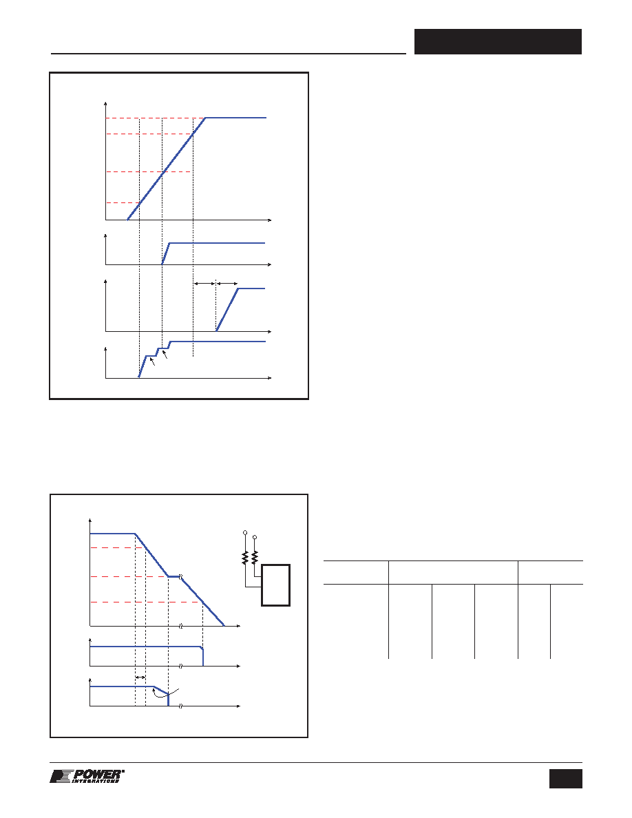
Figure 10. Main and Standby Start-Up.
I EN
(Threshold)
I
LIMIT
R EN (Select)
(1%)
0.0-8.5 mA
L1
500
mA
Open
kW
8.5-17.7 mA
L2
650
mA
280.0
kW
17.7-33.0 mA
L3
750
mA
137.0
KW
33.0-66.0 mA
L4
550
mA
63.4
kW
Table 4.
ENABLE Pin Standby Current Limit Selection.
VIN
Supply Start-Up Sequence
Standby
Output
Main
Output
VBP
12 ms
385 V
315 V
100 V
30 V
2-20 ms
6.0 V
4.7 V
5.7 V
PI-5611a-062710
Figure 11. L and R Pin Duty Limit Mode.
VIN
Standby
Output
Main
Output
385 V
300 V
240 V
40 V
PI-5612a-060910
tHOLDUP
≥ 20 ms
Typically turned off by
secondary supervisor
circuit, once regulation
below limit
t1 t2
t3
t4
RL
RR
To VIN
To Clamp
Reset Circuit
R
HiperTFS
L
相关PDF资料 |
PDF描述 |
|---|---|
| PFS760HG | 3.3 A SWITCHING CONTROLLER, 70 kHz SWITCHING FREQ-MAX, PZIP16 |
| PFS763HG | 4.16 A SWITCHING CONTROLLER, 70 kHz SWITCHING FREQ-MAX, PZIP16 |
| PFS758HG | 2.62 A SWITCHING CONTROLLER, 70 kHz SWITCHING FREQ-MAX, PZIP16 |
| PFS759HG | 2.94 A SWITCHING CONTROLLER, 70 kHz SWITCHING FREQ-MAX, PZIP16 |
| PGA112AIDGSR | SPECIALTY ANALOG CIRCUIT, PDSO10 |
相关代理商/技术参数 |
参数描述 |
|---|---|
| PFS758HG | 制造商:POWERINT 制造商全称:Power Integrations, Inc. 功能描述:Combined Two-Switch Forward and Flyback Power Supply Controllers with Integrated High Voltage MOSFETs |
| PFS759HG | 制造商:POWERINT 制造商全称:Power Integrations, Inc. 功能描述:Combined Two-Switch Forward and Flyback Power Supply Controllers with Integrated High Voltage MOSFETs |
| PFS760HG | 制造商:POWERINT 制造商全称:Power Integrations, Inc. 功能描述:Combined Two-Switch Forward and Flyback Power Supply Controllers with Integrated High Voltage MOSFETs |
| PFS761HG | 制造商:POWERINT 制造商全称:Power Integrations, Inc. 功能描述:Combined Two-Switch Forward and Flyback Power Supply Controllers with Integrated High Voltage MOSFETs |
| PFS7623H | 功能描述:IC PFC CONTROLLER ESIP-16D 制造商:power integrations 系列:HiperPFS?-4 包装:管件 零件状态:在售 模式:连续导电(CCM) 频率 - 开关:22kHz ~ 123kHz 电压 - 电源:10.2 V ~ 15 V 工作温度:-40°C ~ 125°C 安装类型:通孔 封装/外壳:16-SIP,13引线,裸露焊盘,定形引线 供应商器件封装:eSIP-16D 标准包装:30 |
发布紧急采购,3分钟左右您将得到回复。