- 您现在的位置:买卖IC网 > PDF目录10905 > PIC14000T-20/SS (Microchip Technology)IC MCU OTP 4KX14 A/D 28SSOP PDF资料下载
参数资料
| 型号: | PIC14000T-20/SS |
| 厂商: | Microchip Technology |
| 文件页数: | 108/153页 |
| 文件大小: | 0K |
| 描述: | IC MCU OTP 4KX14 A/D 28SSOP |
| 标准包装: | 2,100 |
| 系列: | PIC® 14 |
| 核心处理器: | PIC |
| 芯体尺寸: | 8-位 |
| 速度: | 20MHz |
| 连通性: | I²C |
| 外围设备: | POR,温度传感器,WDT |
| 输入/输出数: | 20 |
| 程序存储器容量: | 7KB(4K x 14) |
| 程序存储器类型: | OTP |
| RAM 容量: | 192 x 8 |
| 电压 - 电源 (Vcc/Vdd): | 2.7 V ~ 6 V |
| 数据转换器: | 斜率 A/D |
| 振荡器型: | 内部 |
| 工作温度: | 0°C ~ 70°C |
| 封装/外壳: | 28-SSOP(0.209",5.30mm 宽) |
| 包装: | 带卷 (TR) |
第1页第2页第3页第4页第5页第6页第7页第8页第9页第10页第11页第12页第13页第14页第15页第16页第17页第18页第19页第20页第21页第22页第23页第24页第25页第26页第27页第28页第29页第30页第31页第32页第33页第34页第35页第36页第37页第38页第39页第40页第41页第42页第43页第44页第45页第46页第47页第48页第49页第50页第51页第52页第53页第54页第55页第56页第57页第58页第59页第60页第61页第62页第63页第64页第65页第66页第67页第68页第69页第70页第71页第72页第73页第74页第75页第76页第77页第78页第79页第80页第81页第82页第83页第84页第85页第86页第87页第88页第89页第90页第91页第92页第93页第94页第95页第96页第97页第98页第99页第100页第101页第102页第103页第104页第105页第106页第107页当前第108页第109页第110页第111页第112页第113页第114页第115页第116页第117页第118页第119页第120页第121页第122页第123页第124页第125页第126页第127页第128页第129页第130页第131页第132页第133页第134页第135页第136页第137页第138页第139页第140页第141页第142页第143页第144页第145页第146页第147页第148页第149页第150页第151页第152页第153页
PIC14000
DS40122B-page 58
Preliminary
1996 Microchip Technology Inc.
Caution:
Reading or writing the ADTMR register
during an A/D conversion cycle can pro-
duce unpredictable results and is not
recommended.
During conversion one or both of the following events
will occur:
1.
capture event
2.
timer overow
In a capture event, the comparator trips when the slope
voltage on the CDAC output exceeds the input voltage,
causing the comparator output to transition from high to
low. This causes a transfer of the current timer count to
the
capture
register
and
sets
the ADCIF
ag
(PIR1<1>).
Note:
The correct sequence for writing the
ADTMR register is HI byte followed by LO
byte. Reversing this order will prevent the
A/D timer from running.
A CPU interrupt will be generated if bit ADCIE
(PIE1<1>) is set to ‘1’ (interrupt enabled). In addition,
the Global Interrupt Enable and Peripheral Interrupt
Enables (INTCON<7,6>) must also be set. Software is
responsible for clearing the ADCIF ag prior to the next
conversion cycle. Note that this interrupt can only occur
once per conversion cycle.
In a timer overow condition, the timer rolls over from
FFFFh to 0000h, and a capture overow ag (OVFIF)
is asserted (PIR1<0>). The timer continues to incre-
ment following a timer overow. A CPU interrupt can be
generated if bit OVFIE (PIE1<0>) is set (interrupt
enabled). In addition, the Global Interrupt Enable and
Peripheral Interrupt Enables (INTCON<7,6>) must also
be set. Software is responsible for clearing the OVFIF
ag prior to the next conversion cycle.
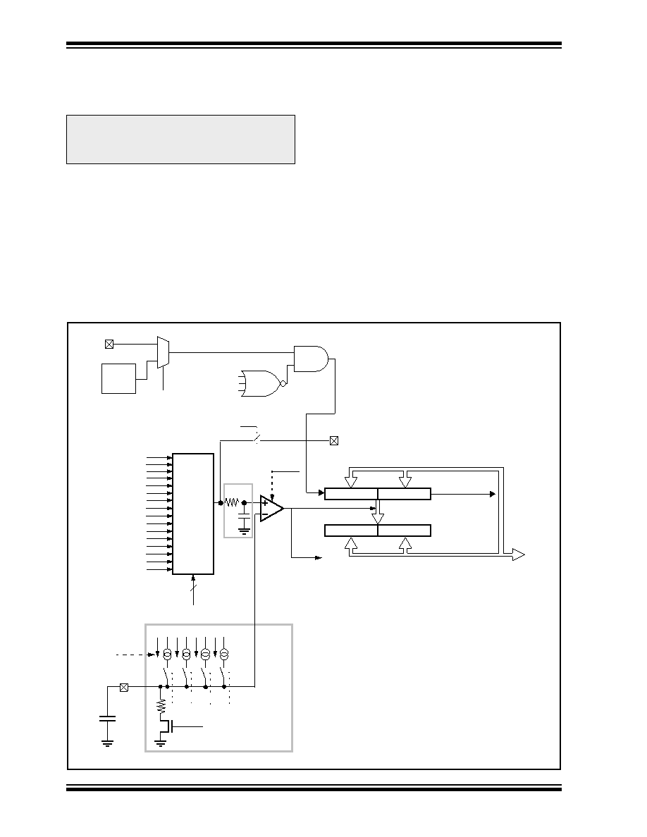
FIGURE 8-1:
A/D BLOCK DIAGRAM
(nominal)
ADOFF
WRITE_TMR
OSC1
1
0
FOSC
(Conguration Bit)
Internal
ADTMRH
ADTMRL
Clock
Stop
Logic
Timer
(OVFIF, PIR1<0>)
ADCAPH
ADCAPL
Oscillator
Analog
Mux
Prog. Ref. A
7
6
5
4
3
2
1
0
Temp sensor
SREFLO
SREFHI
RA2/AN2
RA1/AN1
RA0/AN0
A/D Capture
A/D
Capture Interrupt
ADOFF
CDAC
~2.5uA~5uA~10uA~20uA
ADCON1<7:4>
0.1
F
ADRST (ADCON0<1>)
RA3/AN3
8
~100
ADOFF
Bandgap Ref.
Prog. Ref. B
9
~ 1 kohm
RD4/AN4
RD5/AN5
RD6/AN6
RD7/AN7
10
11
12
13
RESERVED
14
15
AMUXOE
(ADCIF, PIR1<1>)
Overow
Internal
Data
Bus
ADRST
4
Note 2
Note 1:
All current sources are disabled if ADRST = ‘1’
Note 2:
Approximately 3.5 microsecond time constant
Note 1
4-Bit Current DAC
ADCON0<7:4>
(SLPCON<0>)
(ADCON0<2>)
RA0/AN0
相关PDF资料 |
PDF描述 |
|---|---|
| MT5600SMI-X-L-34.R2 | MODEM V.34 SERIAL DATA/FAX 3.3V |
| VE-22V-IY-S | CONVERTER MOD DC/DC 5.8V 50W |
| VE-22T-IY-S | CONVERTER MOD DC/DC 6.5V 50W |
| PIC14000T-20/SO | IC MCU OTP 4KX14 A/D 28SOIC |
| MT100SEM-L.R1-SP | DEVICE SERVER EMBEDDED 3.3V |
相关代理商/技术参数 |
参数描述 |
|---|---|
| PIC-1503 | 制造商:KODENSHI 制造商全称:KODENSHI KOREA CORP. 功能描述:Photo IC(photodiode with signal processing) |
| PIC152N-A | 制造商:SELEC CONTROLS 功能描述:PROCESS INDICATOR,2 ALARMS,1/8DIN,4DIGIT,RELAY OUTPUT |
| PIC152N-B-2 | 制造商:SELEC CONTROLS 功能描述:PROCESS INDICATOR,2 ALARMS,RETRANSMISSION OUTPUT |
| PIC163F73-I/SP | 制造商:Microchip Technology Inc 功能描述:8BIT RISC - Bulk |
| PIC1655A-278 | 制造商:GI 功能描述: |
发布紧急采购,3分钟左右您将得到回复。