- 您现在的位置:买卖IC网 > PDF目录11404 > PIC16C55-XTI/SS (Microchip Technology)IC MCU OTP 512X12 28SSOP PDF资料下载
参数资料
| 型号: | PIC16C55-XTI/SS |
| 厂商: | Microchip Technology |
| 文件页数: | 111/194页 |
| 文件大小: | 0K |
| 描述: | IC MCU OTP 512X12 28SSOP |
| 产品培训模块: | Asynchronous Stimulus |
| 标准包装: | 47 |
| 系列: | PIC® 16C |
| 核心处理器: | PIC |
| 芯体尺寸: | 8-位 |
| 速度: | 4MHz |
| 外围设备: | POR,WDT |
| 输入/输出数: | 20 |
| 程序存储器容量: | 768B(512 x 12) |
| 程序存储器类型: | OTP |
| RAM 容量: | 24 x 8 |
| 电压 - 电源 (Vcc/Vdd): | 3 V ~ 6.25 V |
| 振荡器型: | 外部 |
| 工作温度: | -40°C ~ 85°C |
| 封装/外壳: | 28-SSOP(0.209",5.30mm 宽) |
| 包装: | 管件 |
| 配用: | 309-1026-ND - ADAPTER 28-SSOP TO 28-DIP |
第1页第2页第3页第4页第5页第6页第7页第8页第9页第10页第11页第12页第13页第14页第15页第16页第17页第18页第19页第20页第21页第22页第23页第24页第25页第26页第27页第28页第29页第30页第31页第32页第33页第34页第35页第36页第37页第38页第39页第40页第41页第42页第43页第44页第45页第46页第47页第48页第49页第50页第51页第52页第53页第54页第55页第56页第57页第58页第59页第60页第61页第62页第63页第64页第65页第66页第67页第68页第69页第70页第71页第72页第73页第74页第75页第76页第77页第78页第79页第80页第81页第82页第83页第84页第85页第86页第87页第88页第89页第90页第91页第92页第93页第94页第95页第96页第97页第98页第99页第100页第101页第102页第103页第104页第105页第106页第107页第108页第109页第110页当前第111页第112页第113页第114页第115页第116页第117页第118页第119页第120页第121页第122页第123页第124页第125页第126页第127页第128页第129页第130页第131页第132页第133页第134页第135页第136页第137页第138页第139页第140页第141页第142页第143页第144页第145页第146页第147页第148页第149页第150页第151页第152页第153页第154页第155页第156页第157页第158页第159页第160页第161页第162页第163页第164页第165页第166页第167页第168页第169页第170页第171页第172页第173页第174页第175页第176页第177页第178页第179页第180页第181页第182页第183页第184页第185页第186页第187页第188页第189页第190页第191页第192页第193页第194页
2002 Microchip Technology Inc.
Preliminary
DS30453D-page 21
PIC16C5X
5.1
Power-On Reset (POR)
The PIC16C5X family incorporates on-chip Power-On
Reset (POR) circuitry which provides an internal chip
RESET for most power-up situations. To use this fea-
ture, the user merely ties the MCLR/VPP pin to VDD. A
simplified block diagram of the on-chip Power-On
Reset circuit is shown in Figure 5-1.
The Power-On Reset circuit and the Device Reset
Timer (Section 5.2) circuit are closely related. On
power-up, the RESET latch is set and the DRT is
RESET. The DRT timer begins counting once it detects
MCLR to be high. After the time-out period, which is
typically 18 ms, it will RESET the reset latch and thus
end the on-chip RESET signal.
A power-up example where MCLR is not tied to VDD is
before bringing MCLR high. The chip will actually come
out of reset TDRT msec after MCLR goes high.
In Figure 5-4, the on-chip Power-On Reset feature is
being used (MCLR and VDD are tied together). The VDD
is stable before the start-up timer times out and there is
no problem in getting a proper RESET. However,
too slowly. The time between when the DRT senses a
high on the MCLR/VPP pin, and when the MCLR/VPP
pin (and VDD) actually reach their full value, is too long.
In this situation, when the start-up timer times out, VDD
has not reached the VDD (min) value and the chip is,
therefore, not guaranteed to function correctly. For
such situations, we recommend that external RC cir-
cuits be used to achieve longer POR delay times
For more information on PIC16C5X POR, see
Power-
Up Considerations - AN522 in the Embedded Control
Handbook.
The POR circuit does not produce an internal RESET
when VDD declines.
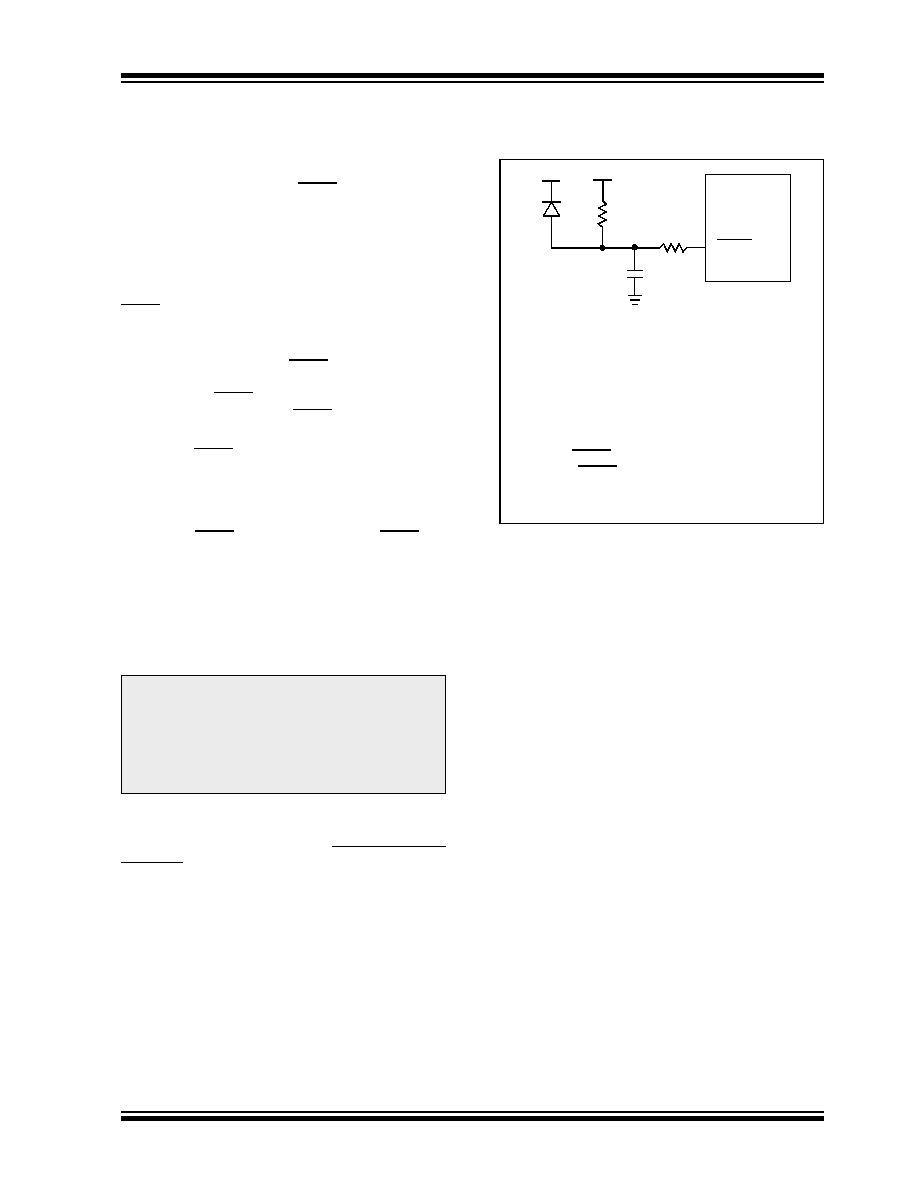
FIGURE 5-2:
EXTERNAL POWER-ON
RESET CIRCUIT (FOR
SLOW VDD POWER-UP)
Note:
When the device starts normal operation
(exits the RESET condition), device oper-
ating parameters (voltage, frequency, tem-
perature, etc.) must be met to ensure
operation. If these conditions are not met,
the device must be held in RESET until the
operating conditions are met.
C
R1
R
D
MCLR
PIC16C5X
VDD
External Power-On Reset circuit is required
only if VDD power-up is too slow. The diode D
helps discharge the capacitor quickly when
VDD powers down.
R < 40 k
is recommended to make sure that
voltage drop across R does not violate the
device electrical specification.
R1 = 100
to 1 k will limit any current flow-
ing into MCLR from external capacitor C in the
event of MCLR pin breakdown due to Electro-
static Discharge (ESD) or Electrical Over-
stress (EOS).
相关PDF资料 |
PDF描述 |
|---|---|
| GRM2196T2A3R5CD01D | CAP CER 3.5PF 100V T2H 0805 |
| GRM2196T2A3R1CD01D | CAP CER 3.1PF 100V T2H 0805 |
| GRM2196T2A2R8CD01D | CAP CER 2.8PF 100V T2H 0805 |
| GRM2196T2A2R6CD01D | CAP CER 2.6PF 100V T2H 0805 |
| PIC18F8393T-I/PT | IC PIC MCU FLASH 4KX16 80TQFP |
相关代理商/技术参数 |
参数描述 |
|---|---|
| PIC16C56/JW | 功能描述:8位微控制器 -MCU 1.5KB 25 RAM 12 I/O RoHS:否 制造商:Silicon Labs 核心:8051 处理器系列:C8051F39x 数据总线宽度:8 bit 最大时钟频率:50 MHz 程序存储器大小:16 KB 数据 RAM 大小:1 KB 片上 ADC:Yes 工作电源电压:1.8 V to 3.6 V 工作温度范围:- 40 C to + 105 C 封装 / 箱体:QFN-20 安装风格:SMD/SMT |
| PIC16C56-10/P | 功能描述:8位微控制器 -MCU 1.5KB 25 RAM 12 I/O 10 MHz PDIP18 RoHS:否 制造商:Silicon Labs 核心:8051 处理器系列:C8051F39x 数据总线宽度:8 bit 最大时钟频率:50 MHz 程序存储器大小:16 KB 数据 RAM 大小:1 KB 片上 ADC:Yes 工作电源电压:1.8 V to 3.6 V 工作温度范围:- 40 C to + 105 C 封装 / 箱体:QFN-20 安装风格:SMD/SMT |
| PIC16C56-10/SO | 功能描述:8位微控制器 -MCU 1.5KB 25 RAM 12 I/O 10 MHz SOIC18 RoHS:否 制造商:Silicon Labs 核心:8051 处理器系列:C8051F39x 数据总线宽度:8 bit 最大时钟频率:50 MHz 程序存储器大小:16 KB 数据 RAM 大小:1 KB 片上 ADC:Yes 工作电源电压:1.8 V to 3.6 V 工作温度范围:- 40 C to + 105 C 封装 / 箱体:QFN-20 安装风格:SMD/SMT |
| PIC16C56-10/SS | 功能描述:8位微控制器 -MCU 1.5KB 25 RAM 12 I/O 10 MHz SSOP20 RoHS:否 制造商:Silicon Labs 核心:8051 处理器系列:C8051F39x 数据总线宽度:8 bit 最大时钟频率:50 MHz 程序存储器大小:16 KB 数据 RAM 大小:1 KB 片上 ADC:Yes 工作电源电压:1.8 V to 3.6 V 工作温度范围:- 40 C to + 105 C 封装 / 箱体:QFN-20 安装风格:SMD/SMT |
| PIC16C56-10E/P | 功能描述:8位微控制器 -MCU 1.5KB 25 RAM 12 I/O RoHS:否 制造商:Silicon Labs 核心:8051 处理器系列:C8051F39x 数据总线宽度:8 bit 最大时钟频率:50 MHz 程序存储器大小:16 KB 数据 RAM 大小:1 KB 片上 ADC:Yes 工作电源电压:1.8 V to 3.6 V 工作温度范围:- 40 C to + 105 C 封装 / 箱体:QFN-20 安装风格:SMD/SMT |
发布紧急采购,3分钟左右您将得到回复。